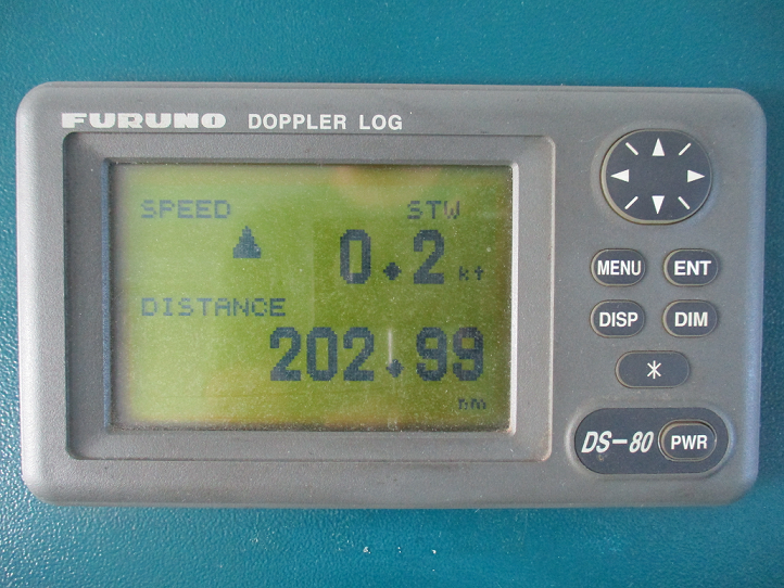
The speed log is a device used to measure the speed and also the number of nautical miles the vessel has travelled through the water in a given time.
Type of speed measurements
This is the speed of the vessel with respect to the solid earth.
All satellite navigation systems (GPS,GLONASS, etc) provide speed over ground.
It is an important piece of information for navigation , especially for antigrounding purposes.
Speed over water
Most speed logs, discussed later in this module, provides speed over water.
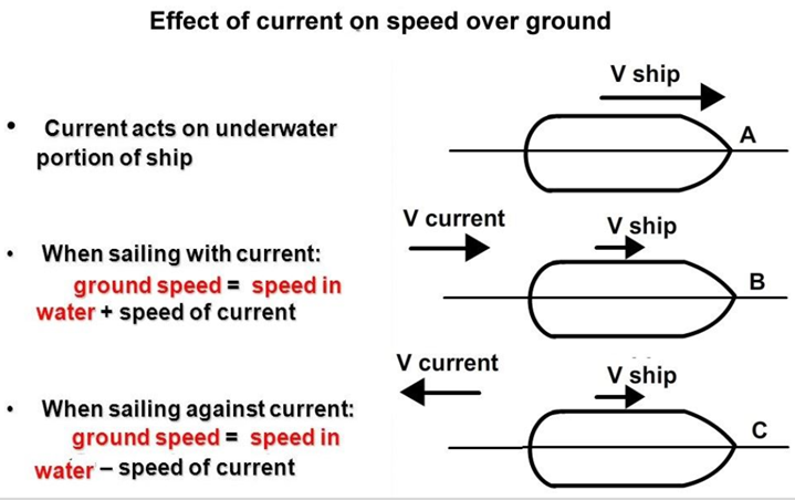
To put in simple terms, speed over water is the resultant of the ship’s speed over ground and the speed of the current or effect of wind prevailing at that time.
Speed over water is an important piece of information for collision prevention purposes and is a compulsory input for Radar.
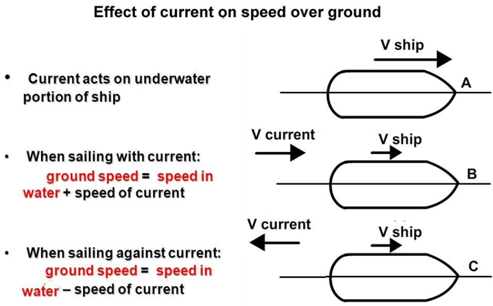
The diagram shows the effect of current or wind prevailing at that time on ground speed and explains the difference between speed over ground and speed over water.
Doppler Log
Doppler log works with the principle of Doppler effect. When a sound bean is transmitted from a moving vessel, a difference (shift) in the frequencies is observed between transmitted sound and its reflected echo from the sea bed.
This frequency shift is known as the “Doppler shift”. The degree of shift in the frequency is proportional to the speed of the vessel.
Principle of Doppler Log
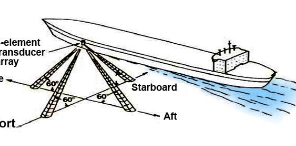
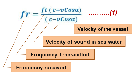
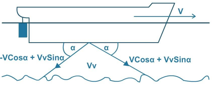
A Transducer is fitted on the ship’s keel which transmits a beam of acoustic wave at an angle, usually 60°, to the keel in the forward direction, this gives the component vCosἀ of the ship’s velocity towards the sea bed thus causing the Doppler shift of the received frequency which can be calculated by:
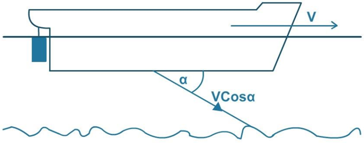
If the waves are transmitted directly towards the seabed, perpendicular to the keel, there will be no Doppler shift.
This is because there will be nor relative approach between the source and reflecting surface, hence the transmitted and received frequency will be the same.
This can also be proved mathematically with cos 90° = 0 in the above equation “fr will be equal to “ft
After applying binomial expansion theory and considering that vCosἀ is much smaller compared to “c” equation 1 can rewritten as:
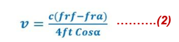
With the help of this formula we can calculate the speed of the ship, considering that there is no vertical motion.
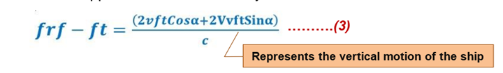
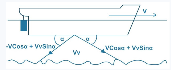
In practice the ship has some vertical motion and the Doppler shift measurement will have a component of this vertical motion.
This problem is addressed by using two transducers one looking forward and the other looking aft. Such arrangement is called Janus Configuration.
In this case Doppler shift measurement by the forward transducer will be:
The transducer fitted looking aft will register a Doppler shift measurement as

JANUS CONFIGURATION
When a ship pitches the forward and aft part of the ship oscillated; such that when the forward part is travelling downwards the aft part will travel upwards and vice versa. Therfore if we calculate the difference between equations 3 and 4 the vertical component Vvftsinἀ will cancel out and the horizontal component will add up and the final form of the equation will be:
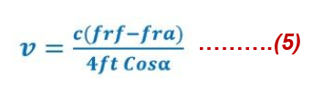
Thus v, i.e speed of the ship can be calculated.
The speed of the ship as determined by the above formula is the speed over ground, unaffected by set and drift of the prevailing since the echoes are coming from the seabed.
This is also referred to as bottom track or ground track.
The transmitted pulse with its limitation in power and can reach upto a depth of usually 200 meters. Beyond this depth, the echoes from the seabed become very weak and hence the strength to calculate the Doppler shift.
Interestingly, echoes are also available from water layers between 10 and 30 meters below the keel.
When the ship moves at her usual full-speed it carried some mass of surrounding water with it and thereby providing a distinct interface at a depth of about 20 meters between moving and still water. This interface acts as an echoing surface of the acoustic waves. These echoes are weak since the echoing surface is liquid, but stronger than the echoes coming from the depths of over 200 meters and enough to measure Doppler Shift.
The speed obtained from this layer is speed over water i.e to say it affected by set and drift of the prevailing current.
The equipment automatically changes over to water track when the echoes from the sea-bed are not strong enough.
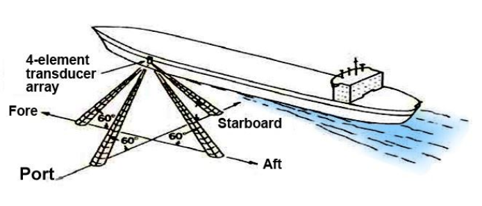
Athwartship’s Speed (port- starboard)
Doppler log on ground track mode can provide atwart ship speed as well and for this purpose a similar Janus configuration is used on the port and starboard sides.
The athwart ship speed is calculated in the similar manner as the forward and aft speed.
Factors affecting accuracy of Doppler log
Heaving
Any vertical movement Vv will have a component Vvft sin ἀ in the direction of the acoustic wave. During heaving the forward end and the aft end will travel upward and downward together.
The Vvft sin ἀ component from both trandicers, therefore, instead of cancelling will add up. This will eventually result in error in speed measurement.
Error in transducer orientation
The transducers should make a perfect angle of 60° with respect to the keel or else the speed indicated will be inaccurate.
Error in oscillator frequency
The frequency generated by the oscillator must be accurate and constant, any deviation in the frequency will result in the speed indicated being in error.
Error in propagation velocity of acoustic wave
The velocity of the acoustic wave at the temp of 16°C and salinity of 3.4% is 1505 m/sec, but generally it is taken as 1500 m/sec for calculation. This velocity changes with temperature ,salinity or pressure.
To compensate the error due to temperature variation, a thermistor (ie a resistance whose value changes with temperature) is mounted near the transducer and change in velocity of the acoustic wave through water from the standard value due to the change in sweater temperature is accounted for.
Errors due to ship motion
During the interval between transmission and reception, the ship may marginally roll or pitch and thereby the angle of transmission and reception can change.
The net effect will be an error of 0.10% of the indicated speed which is marginal and can be neglected.
Error due to inaccuracy in measurement of comparison frequency
The difference in the frequencies received by the forward and aft transducers must be measured accurately as any error in this will be directly reflected in the speed of the vessel.
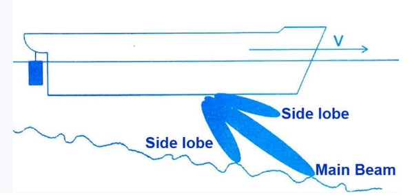
Error due to side lobe
When the side lobe reception dominated over the main beam reception, there will be an error in the speed indicated.
This error is more pronounced on a sloppy bottom, where the side lobe will be reflected at a more favorable angle and will have path length less than the main beam.
Наиболее стильные новости индустрии.
Важные мероприятия лучших подуимов.
Модные дома, торговые марки, высокая мода.
Свежее место для стильныех хайпбистов.
https://rftimes.ru/news/2024-04-14-prirost-zabolevaemosti-koronavirusom-protivoyadie-kotorogo-ne-zhdali-mediki-obespokoeny-vspyshkoy-virusa
0901 https://vladnews.ru/2023-11-16/227949/demna_gvasaliya https://msk.rftimes.ru/news/2024-05-29-tragediya-v-rezultate-operatsii-22-letnyaya-studentka-iz-ufy-umerla-ot-sepsisa
https://rftimes.ru/news/2023-11-24-rossiyskiy-flot-srazhaetsya-s-vooruzhennymi-silami-ukrainy-v-chernom-more
https://kostroma.rftimes.ru/news/2024-05-18-noch-muzeev-perenesli-iz-tsentra-kostromy-na-vystavku-svo
196 https://vladnews.ru/2023-11-16/227949/demna_gvasaliya https://vladtoday.ru/news/2023-12-05-vo-vladivostoke-ostanovleno-teplosnabzhenie-i-goryachaya-voda-dlya-8-tys-chelovek/