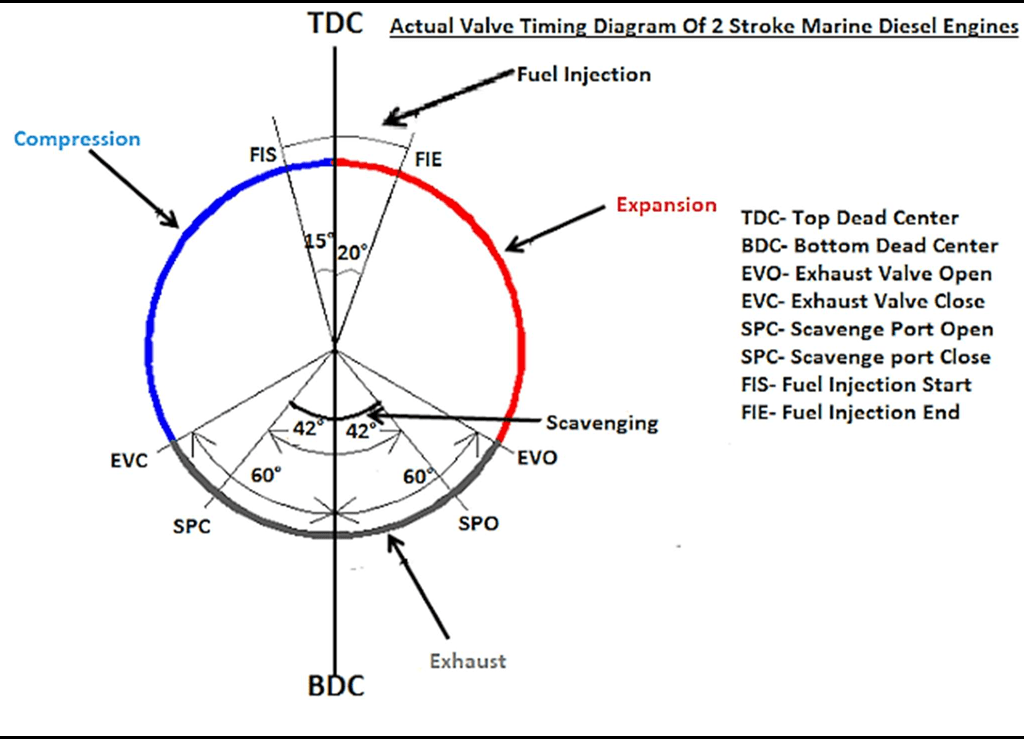
Timing diagram of a two stroke diesel engines. Principle of operation of 2 stroke engine
Description:
- Scavenge port opens 42°C before BDC.
- Piston reaches BDC.
- Scavenge port closes 42°C after BDC.
- Exhaust valve closes 60°C after BDC.
- Around 15°C before TDC fuel injection starts.
- Piston reaches TDC.
- Around 20°C after TDC fuel injection stops.
- Then, exhaust valve opens 75°C before BDC
Large 2 stroke diesel engine
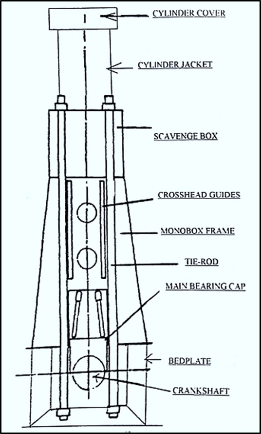
Crankshaft:
- It is a rotating part that sits on top of the engine bedplate.
- It connects every unit of main engine through a connecting rod arrangement.
- Connecting rod allows to receive and transfer power between all units.
Bedplate:
- It is a structure which forms the base of an engine upon which the bearings and frame are mounted.
- The bedplate consists of high, welded longitudinal girders and cross girders with cast steel bearings support
Main Bearing Caps:
- Located at the bottom of the engine block and holds the main bearings in place.
- It is constructed in such a way as to allow the oil to flow through the piston and crankshaft in a thin layer.
Tie Rod:
- It’s a long rod with tie bolts at both ends.
- This rod holds three major engine components – Cylinder block, ‘A’ frame and crankcase in compression cycle and transmits the firing load to the bedplate.
Crosshead Guides:
- It is a block or bar between the piston and connecting rod.
- It prevents piston from moving from side to side and damaging the piston and cylinder.
Principle of operation of 2 stroke engine. Why is 2 stroke engines preferred for use as main propulsion engine?

Principle:
- The fuel is burn within the combustion chamber of the engine.
- Combustion of fuel and conversion of heat energy from combustion to mechanical energy takes place within the cylinder.
Operation / Stages
- Supply of fresh air to the cylinder (Scavenging)
- Compression of air above bar, so that temperature of air rises (about 550° C) to the self-ignition temperature of the fuel. (Compression Stroke)
- Fuel injection is done. Fuel mixes with air, burns and gives out heat and this is called combustion.
- Hot high-pressure gases produced pushes the piston downwards towards the end of the stroke (Power Stroke)Piston moves down, uncovers the exhaust ports, exhaust gas blown out. (Exhaust).
Reason for two stroke engine preference:
- Two stroke engines have a higher power to weight ratio than four stroke engines.
- This means, two stroke engines produce more power relative to their weight in comparison with four strokes.
- Two stoke engine can run either clockwise or counter-clockwise. This cannot be done in four-stroke engine.
Scavenging system for large 2-stroke engines

Scavenging:
Scavenging is supplying of fresh air to the cylinder for compression and thereby for combustion of fuel injected and removal of exhaust gas.
Scavenging Types:
- There are a number of different scavenging methods in use in two stroke engines.
- Three basic systems in use are – Cross flow, Loop and Uniflow.
- All modern engines use uniflow scavenging system with a cylinder head exhaust valve.
Cross Scavenging:
- Exhaust ports are first to get uncovered when piston is travelling downwards.
- Exhaust gases are blown down through open exhaust ports.
- Then air inlet ports open, this pushes the left-over exhaust gases out and now the space is filled with fresh air.
Loop Scavenging:
- Here exhaust port and inlet port are located on the same side. The process is pretty similar…
- Left over exhaust gases after initial blow down are scavenged out by incoming air from uncovered scavenge air inlet ports.
Uniflow Scavenging:
- Air inlets are located at the bottom of liner on both sides.
- Exhaust gases are blown though cylinder head exhaust valve.
- Exhaust valve open by cam shaft mechanism.
Principle of operation of four stroke engines.
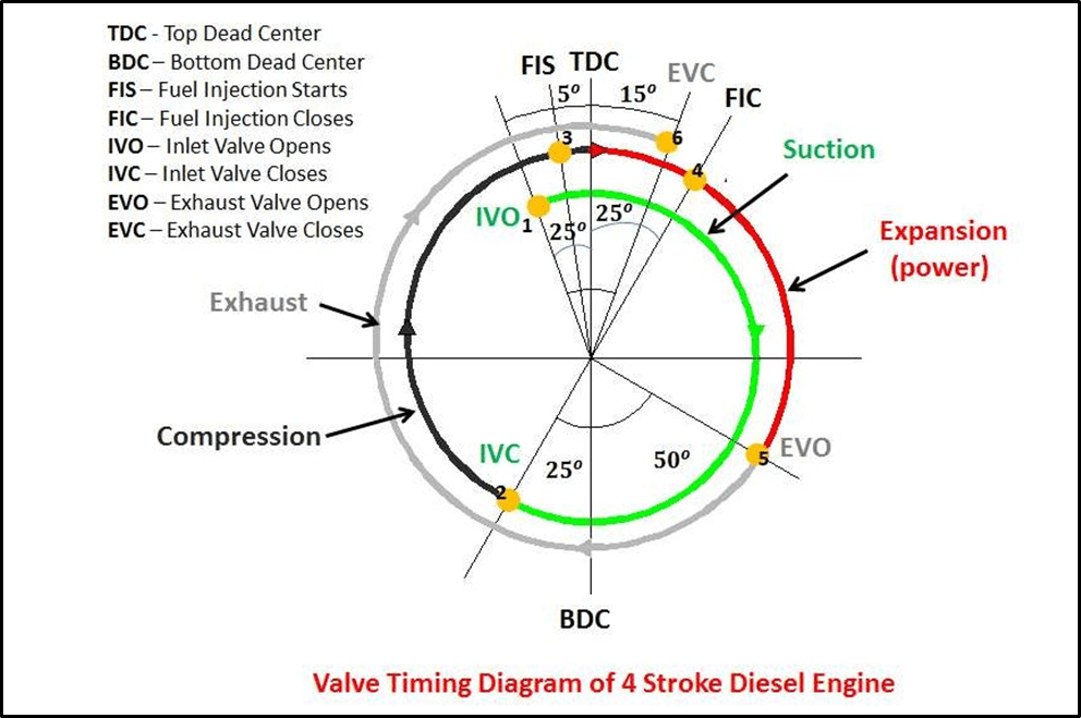
- Inlet valve opens 20° before TDC.
- Piston reaches BDC
- Inlet valve closes 6ۣ0° after BDC
- Injection starts 10° before TDC.
- Piston reaches TDC
- Injection ends 12° after TDC.
- Exhaust opens 42° before BDC.
- Piston reaches BDC.
- Scavenging is going on and piston reaches TDC
- Exhaust closes 60° after TDC.
Differences between 4 stroke and 2 stroke engines
| TWO STROKE ENGINES | FOUR STROKE ENGINES |
| Combustion cycle is completed in two strokes | Combustion cycle is completed in four strokes. |
| Hight power to weight ratio. | Lower power to weight ration. |
| Reversing gear not required. | Reversing gear required. |
| Lighter flywheel | Heavier flywheel |
| Low LO consumption. | Higher LO consumption. |
| Low noise level. | High noise level. |
| Higher emission of unburned CH and NOx | Lower emissions due to better combustion efficiency |
| More frequent maintenance. | Longer maintenance intervals. |
| Cheaper installation cost, but high maintenance cost. | Higher installation cost, lower operational cost. |
| More chances of scavenge fire. | Less change of scavenge fire. |
| High vibration problems due to long stroke. | Low vibrations. |
| Normally used as propulsion engines. | Normally used on generators. |
Indications of Scavenge fire on 2 Stroke Diesel Engines? What action to be taken in case of Scavenge fire?
Scavenge Fire:
- Fire in the scavenge space is caused due to the presence of cylinder oil, unburned fuel, and carbon.
- Unburned fuel and carbon may be due to defective piston rings, faulty timing, defective injector etc.
- Hot gases from the cylinder or hot piston may ignite these mixture and cause scavenge fire.
Indications:
- Loss of engine power.
- Scavenge space temp alarm sounds
- Dark smoke in exhaust
- High exhaust temperature.
- Turbo chargers may surge and sparks will be seen at scavenge drains.
- Irregular running of engine (engine running note changes)
Action:
- Once detected, slow down main engine.
- Shut off fuel to the affected cylinder.
- Close all the scavenge drains.
- Small fire will quickly burn out, but where the fire persists, engine must be stopped.
- Fire extinguishing medium should be injected through the fittings provided in the scavenge trunking.
- On no account should the trunking be opened up.
- Seizure of engine moving parts may take place and thus, it is advisable to keep the engine turning on turning gear.
Prevention:
- Engine timing for fuel injecting, exhaust opening, cylinder lubrication etc. must be correct.
- Regular maintenance must be carried out.
- Scavenge trunking must be regularly inspected and cleaned if necessary.
- If carbon or oil build up is found, source should be identified and fault remedied.
- Blow down scavenge drains and any oil discharges must be investigated.
Three types of indicator cards taken for a main engine on board a ship
Indicator Card:
- An indicator diagram is a pressure/volume graph taken from the variations of pressure in the cylinder of an engine.
- It is plotted as a continuous line showing all pressure changes during one compete engine cycle.
- Indicator diagrams are used to assess the performance of each unit of the ship’s main engine and thereby assessing the overall performance of the engine.
- Engine indicator is an instrument using which indicator diagrams are drawn.
- Four types of indicator diagrams can be obtained.
- Power card, compression diagram, draw card, light or weak spring diagram.
Power Card:

- It is a measurement of the variation of pressures in a cycle.
- Irregularities in the shape of the diagram will show operational faults.
Compression diagram:
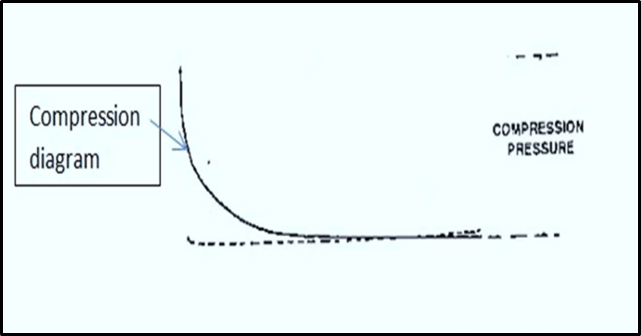
- Compression diagram is taken in a similar manner to the power card but with the fuel shut off from the cylinder.
- Reduction in the height of this diagram shows low compression, which may be due to worn cylinder liner, faulty piston rings, insufficient scavenge air or leaky exhaust valve.
- Any of these will cause poor combustion.
Draw card or out of phase diagram

- Taken similar to power card, but with fuel pump engaged but with indicator drum 90°C out of phase piston stroke.
- This diagram indicates more clearly the pressure changes during fuel combustion.
- Fuel timings or injector faults may be detected from its shape.
Light or Weak spring diagram:

- Light compression spring is fitted to the indicator and measurements are taken similar to power card.
- This diagram shows pressures changes during exhaust and scavenge to an enlarged scale.
- Can be used to detect faults and scavenge to an enlarged scale.
“Internal Combustion Engine”? Why pre-heating of main engine is carried out?
Internal Combustion Engine:
- An internal combustion engine is one, in which fuel is burnt within the combustion chamber of the engine.
- Combustion of fuel and conversion of heat energy from combustion to mechanical energy takes place within the cylinder.
Pre-heating of main engine:
- If the engine is preheated, it can easily reach the self-ignition temperature of the fuel, thus firing immediately.
- Also, less starting air is required, thus giving more reserve of air for further movements.
- Minimises any cold corrosion.
- Minimises stresses due to uneven expansion, during starting.
- When the engine is warm, clearances are correct, thus lubrication is made easier, and there is less chance of under wear of moving parts.
- It has been found that maximum wear takes place during the starting period of any machinery, since lubrication is not adequate.
Step by step development of a crank case explosion
- For an explosion to occur, there must be air, fuel and ignition.
- However, if a mechanical fault develops with the consequent rubbing of moving parts then a hot spot will occur in the crankcase.
- When the temperature of hot spot reaches 200°C the lubricating oil splashing on to this hot spot vaporises.
- The vapour then circulates to the cooler parts of the crankcase where it condenses to form an oil mist.
- A white mist formed, mixed with crankcase air circulates back to hot spot.
- If mist is at right concentration with air, it is ignited.
- This is called a Crankcase Explosion
- This flame front further vaporizes oil droplets
- A pressure shockwave is built up
- If not relieved, it ruptures crankcase doors and air is drawn in
- A secondary or major explosion occurs resulting in bigger damage
Crank case relief valve fitted on a large IC engine

Purpose:
- When the internal pressure of the crankcase increases between 0.2 to 1 bar, the valve lifts and relieves the pressure.
- It also prevents the ingress of fresh air as it is a non-return valve.
- Crankcase relief valves are fitted with flame arrestor which prevents exit of flame outside the engine.
Working:
- The crankcase relief valve consists of a light spring that holds the valve closely against its seat.
- The whole arrangement is enclosed in a cover, which is tightly bolted from all the sides.
- The assembly is mounted on the door of the crankcase.
- On the outside of the valve a deflector is fitted which safeguards the personnel from escaping pressurized gases.
- On the inside of the engine, an oil wetted gaze acts as a flame trap to prevent any flame leaving the crankcase.
- When the pressure inside the crankcase increases, the valve raises compressing the spring.
- The excess pressure is released to the atmosphere.
- The oil wetted gauze assembly prevents the flame in the crankcase from escaping.
- The valve closes automatically under the tension and action of spring once the pressure reduces.
Protection / Precautions against Crank Case Explosion
- Regular inspection of crankcase for oil flow through bearings and oil jet nozzles
- Crankcase doors must be fastened sufficiently and be of sufficient strength so that they do not get displaced by crankcase explosion.
- Crankcase explosion relief valves must be fitted with flame arrestors.
- Crankcase oil mist detectors and monitoring equipment are provided.
- OMD gives alarm and also indicate the unit where the mist level is high.
- Such High-level alarm also initiates engine slow down.
- Low level alarm is just an alarm only.
- High bearing temperature alarms are provided.
- Regular testing of mist detector, alarm and crankcase relief valve as per maker
- Maintaining engine lubricating oil in good condition, free from fuel oil contamination
- Warning notices provided on crankcase doors indicating doors not be opened immediately if overheating is suspected.
- Crankcase ventilation pipes where provided are small and practicable.
Proper lubrication bearings inside the crank case important to prevent crank case explosion? What are the regulatory requirements to prevent crank case explosion related accidents on ships?
Importance of adequate lubrication:
- Oil mist and hot spots are the combination to cause crank case explosion.
- Hot spots occur due to metal to metal contact between moving elements in the crankcase.
- Lack of clearance between bearings, will lead to lube oil starvation resulting in increase in bearing temperature.
- The purpose of lube oil is not only to reduce friction, but also to carry away heat generated by the process.
- Thus, proper lubrication is required to avoid metal to metal contact and dissipate excess heat.
- LO quality and correct quantity must be maintained in order to achieve the desired function.
- Lubrication plays a vital role in avoiding hot surface for the crank case explosion to occur.
Regulatory requirements:
Crankcase Relief Valve Requirements:
- As per SOLAS, the internal combustion engine of a cylinder diameter of 200mm or crankcase volume of 0.6m3 and above shall be provided with crankcase relief valve.
- When the cylinder diameter is more than 30cm, relief valve shall be fitted on each crankcase door.
- Minimum spring setting for lifting the relief valve shall be 0.07 bar.
- The valves should open smartly and close positive and rapidly.
- Relief valve shall be arranged or provided in such a way that minimises injury to personnel due to its discharge.
Oil Mist Detectors Requirements
- Engines of 2250KW and above or having cylinders of more than 300mm bore shall be provided with crankcase oil mist detectors, engine bearing temperature monitors or equivalent devices.
- Oil mist detectors shall be capable providing high level alarm and initiate slow down procedures for low speed diesel engines of 2250 kw and above.
- Oil mist detectors shall be capable providing high level alarm and initiate auto shutoff for high speed diesel engines of 2250 kw and above.
Fuel oil system used for Propulsion of main engine
Description of Fuel Oil System:
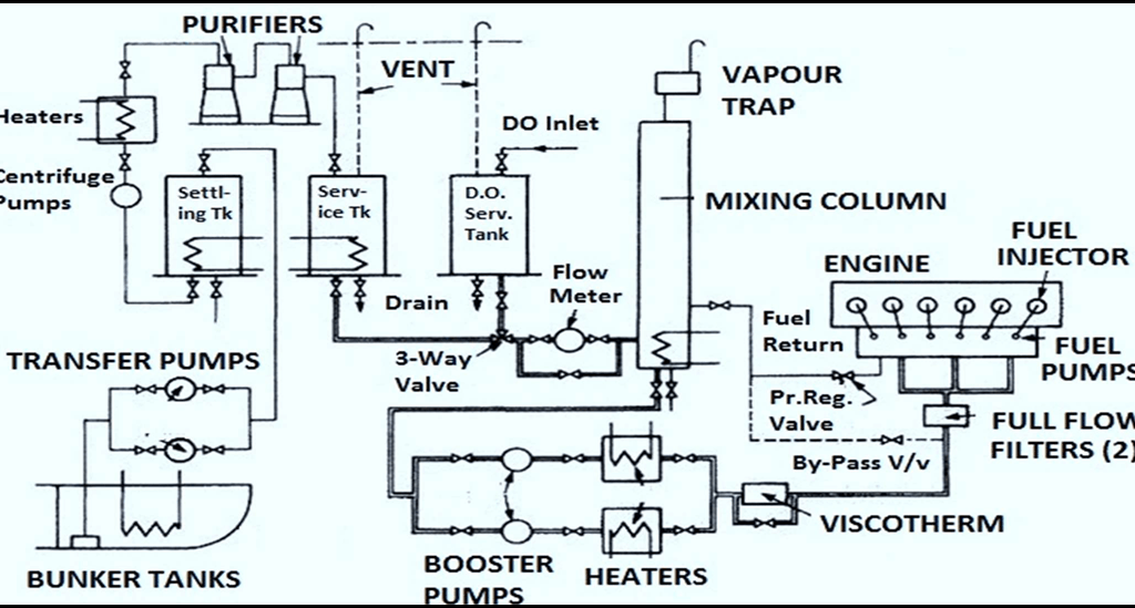
- The fuel oil system consists of bunker tanks → transfer pumps → settling tanks → purifier → supply pumps →mixing column → booster pump → fuel pumps → circulating pumps.
- The fuel oil is stored in Bunker tanks, from where it is transferred by the Transfer pumps to the settling tanks. Here, the oil is heated and drained of water.
- The Purifiers take suction from the Settling tank, and fill up the Service tanks with purified oil. Separate service and settling tanks are provided for heavy fuel oil and diesel oil.
- The supply pumps transfer the purified oil (HFO or DO) from the service tank to the Mixing Column, through a change-over valve (3-way valve).
- The booster pumps take suction from the Mixing Column, and send the fuel to the fuel pumps through the heaters and Viscotherm (viscosity regulator), which monitors the viscosity and controls the heating to maintain the viscosity for proper combustion of the fuel. A full flow filter (with a by-pass filter) is provided just before the fuel pumps.
- The unused oil is returned either to the service tanks or to the mixing column.
- The fuel pumps on the engine deliver the fuel to the fuel injectors via high pressure pipes.
- Two supply pumps and two booster pumps are provided. All of these are positive displacement pumps.
- Modern engines are provided with recirculation system, whereby heated fuel is kept circulating even when engine is stopped.
- System is protected by various temperature transmitters, pressure transmitters and level transmitters.
- Mainly pressure sensors are provided at the discharge side of all the pumps to detect low pressure.
- Temperature sensors are provided for the bunker tanks, settling and service tanks and purifier heaters to indicate high temperature.
Use of various parts in above system viz. filters, purifiers, quick closing valves, heaters, fuel pumps
Fuel Oil Filters:
- Filters are used for fine filtration of smaller particles
- Filters are mounted in pairs. One would be in operation and the other as a standby.
- Filters are made of natural or synthetic fibrous material and will be in a cylindrical arrangement.
Quick Closing Valves:
- QCV’s are fitted on settling and service tanks.
- The purpose of such valves is that, in the event of fire, they may be safely closed from remote location to prevent fuel in the tank from feeding the fire.
- They are also used to isolate a tank from the fire.
- QCV’s are operated remotely by pull wires, hydraulics or compressed air.
Heaters:
- Purpose of heating the fuel oil is
- To ensure smooth pumpability at different stages.
- To favour combustionTo achieve oil ignition temperature.
- Heaters are used to heat the fuel oil to maintain its temperature around 40°C (for HFO).
- Further heating is done in settling tank to ensure it is at appropriate temperature to enter the separators.
- When the fuel is transferred to the service tank from the separator, the oil temperature is >80°C.
Fuel Pumps:
- The booster pumps take suction from the Mixing Column and send the fuel to the fuel pumps through the heaters and Viscotherm (viscosity regulator), which monitors the viscosity and controls the heating to maintain the viscosity for proper combustion of the fuel.
- A full flow filter (with a by-pass filter) is provided just before the fuel pumps.
- The fuel pumps on the engine deliver the fuel to the fuel injectors via high pressure pipes.
Mixing Column:
- Fuel oil from service tanks passes through flow meter to the mixing column.
- Unused fuel from the main engine from fuel injector returns to the mixing column.
- Fuel oil mixes with returned fuel from the main engine.
- Mixing column acts as a buffer tank for excess fuel.
- Purpose is to produce gradual variation of fuel quantity during changeover period from DO to HFO or vice versa by mixing.
- The mixing column is fitted with a relief valve and an air release.
- The throughput of supply pump is twice the consumption of main engine, so oil is always coming and mixing column is always full.
- Mixing column maintains heating of circulating fuel.
- A sufficient head pressure is maintained in mixing column to prevent air entering the system.
Various Piping Systems found on board in Engine room of a ship. Description of the cooling water system of main engine.
Piping System:
- Lubricating oil systems
- Fresh water-cooling system
- Sea Water cooling system
- Starting air system
- Bilge and Ballast System
Cooling water system:

Cooling Water System:
- Cooling of engine is required to enable the engine metal to retain their mechanical properties.
- The usual coolant used is fresh water.
- Seawater is not used directly as a coolant because of its corrosive action and tendency of scale formation in narrow cooling passages.
- Lubricating oil is sometime used for piston cooling since leaks into crankcase would not cause problems.
- In FW cooling system, freshwater is circulated around through internal passages within the engine.
- The cooling liquid is thus heated up and is in turn cooled by seawater at a cooler.
Lubricating oil system for a 2 stroke diesel engine

Lubricating oil system:
- Lubricating oil for the engine is stored in the lube oil storage tanks, and the oil in use is in the sump.
- The oil is drawn from the sump through a strainer by the lube oil pumps and filtered before passing through the cooler and thence to the engine.
- This may be distributed to various bearings and other lube points inside the engine.
- An alarm system ensures that adequate lube oil pressure is always maintained while the engine is running.
- After use in the engine the lube oil drains back into the sump.
- A centrifuge is provided for purifying the system oil.
- The lube oil cooler may be either seawater cooled or by means of central cooling system