SOLAS requirements for steering gear
- All vessels must be provided with efficient main and auxiliary steering gear of power operated type.
- An auxiliary gear is not required if the main gear is provided with duplicate power units and duplicate connections up to the rudder stock.
- The main steering gear must be able to steer the ship at maximum ahead service speed and be capable at this speed, and at the ship’s deepest service draught of putting the rudder from 35° on one side to 30° on the other side in not more than 28 sec.
- Power operated gears must be fitted with a device to relieve shock.
- Electric leads and fuses are to allow 100% overload.
- Moving parts of steering gears should be guarded to avoid injury to personnel.
- Hydraulic systems should employ non-freezing fluid.
- Hydraulic system should be provided with low-level alarm and fixed storage tank.
- One motor should be connected to Emergency Switch Board.
- A clear view from the steering position is required.
- Every oil tanker, chemical tanker and gas carrier of 10,000 GT and upwards shall comply with the single failure criteria i.e. safematic design of steering system.
- That is, no single failure on a steering should make the steering of the ship inoperative and thus give the rudder a chance to become free.
How a rudder order signal results in achieving the desired rudder angle
- In the steering system, the steering gear provides a movement of the rudder in response to a signal from the bridge. The total system may be considered made up of three parts:
- Control Equipment
- Power unit
- Transmission to the rudder stock.
- Control equipment conveys a signal of desired rudder angle from the bridge to the steering flat.
- The signal activates the power unit and transmission system until the desired angle is reached.
- Power unit provides the force when required and with immediate effect to move the rudder to the desired angle.
- Transmission system (steering gear) is the means by which the movement of the rudder is accomplished
Hunting Gear:
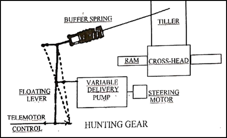
- Initially the steering gear pumps are in a no-delivery state.
- When a rudder movement is received from the bridge telemotor transmitter, the telemotor receiver cylinder will move the floating lever.
- Floating lever will move the floating ring in the variable delivery steering pump.This causes a pumping action and moves the tiller.
- The return linkage via buffer spring will cause the floating lever to be re-positioned.
- This re-positioning will cease the pumping when the required rudder angle is reached.
Two ram steering system
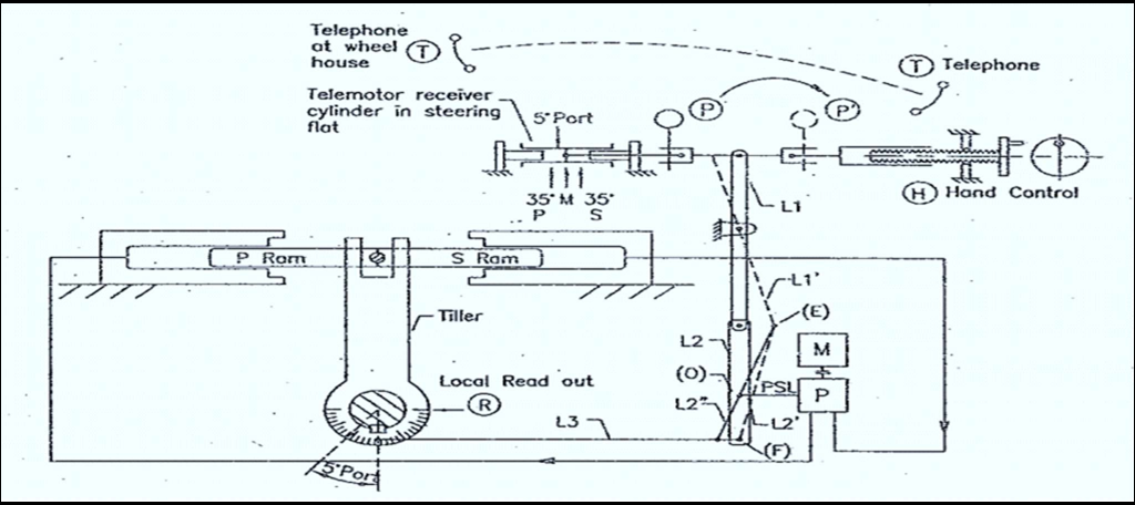
Working:
- This steering gear consists of 2 rams, a pump and a motor.
- On receiving a signal of 5°P from the wheelhouse, the telemotor receiver cylinder placed in the steering flat will to left equal to 5°P.
- Lever is initially in a straight line. Once the steering flat moves, Lever L1 will move to L1’, Lever L2 will move to L2’ as shown in the figure.
- Due to the above movement, pump stroke lever (PSL) will get pushed into the pump. Pump will start pumping into left hand cylinder and draws from right hand cylinder.
- This will cause RAM’s to slide from left to right. Rudder will start moving towards port.
- As the rudder moves towards port, the lever L1 will be drawn along towards left side.
- The rudder will keep moving till 5°P, the lever L3 would pull in the lever L2 from L2’ to L2’’ (about point E) and subsequently the pump stroke lever (PSL) back to zero pumping position ‘O’.
- Pump now will not be pumping and the rudder will therefore be hydraulically locked at 5°P.
- When helm is put to midship, the receiver cylinder in steering flat will spring back to midship position, the receiver cylinder in steering flat will spring back to midship position.
- Lever L will come from L1’ to L1 position and subsequently the pump will again start pumping, this time into starboard cylinder, till the rudder comes back to midship position.
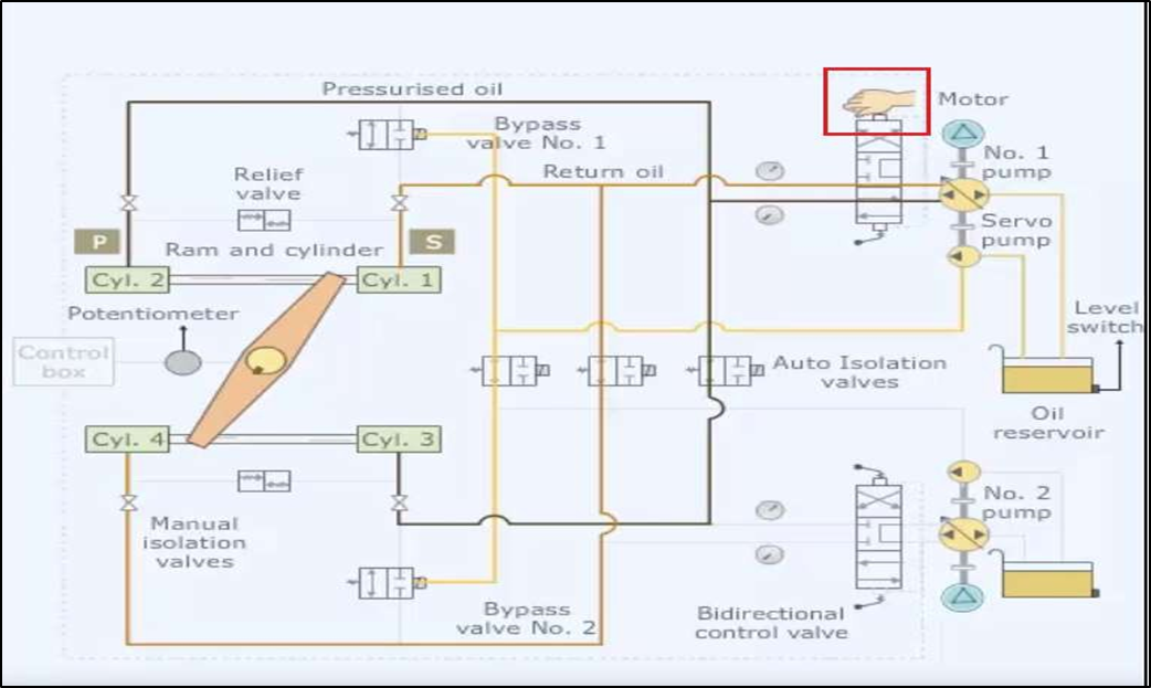
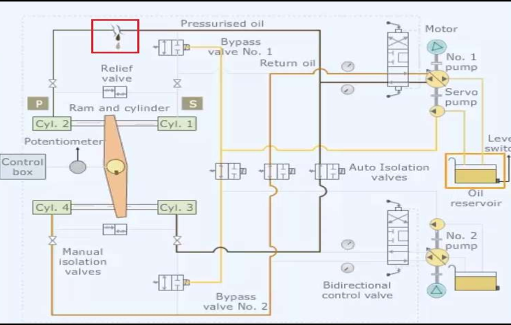
4-ram hydraulic steering gear system
Description of the system:
- There are two sets of hydraulic power packs comprising of hydraulic pumps and oil reservoir.
- Bi-Directional control valve changes the direction.
- Automatic and manual isolation valves isolate the defective system in case of emergency.
- Bypass valves for each set of rams bypass the defective rams when isolated.
- Relief valves maintain the system oil pressure within limits.
- The control box receives helm order from bridge and sends electric signals to directional control valve.
- Pressurised Hydraulic oil is supplied to the cylinders.
- The tiller arm converts the linear motion of the rams into rotary motion of the rudder stock.
- Potentiometer senses the rudder stock position and sends a feed back to control box.
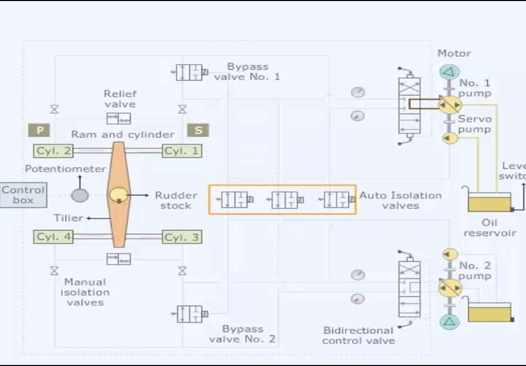
Working:
- When one of the steering pump motors is started, the main pump and the servo pump start running.
- Electrically operated isolating valves are kept in open position.
- Bypass valve is actuated to close position by the oil supplied by the servo pump.
- When no helm is ordered, the bidirectional control valve is in mid position.
- When port order is given from the bridge, the control box sends a signal to the bidirectional control valve that moves to the forward side.
- Pressurized oil is pumped into ram 2 and 3. The pressurized oil moves the ram.
- The tiller in turn moves the rudder stock from the mid-ship to port position.
- The returned oil from ram 1 and 4 flows back to the pump return side.
- When the rudder stock reaches the desired “helm angle”, the potentiometer sends a signal to the control box.
- The control box sends a signal to bidirectional control valve.
- The valve is pushed back to its initial position.
- Similarly, when starboard order is given, ram 1 & 4 are moved.
- Returned oil after moving the ram flows back through return line.
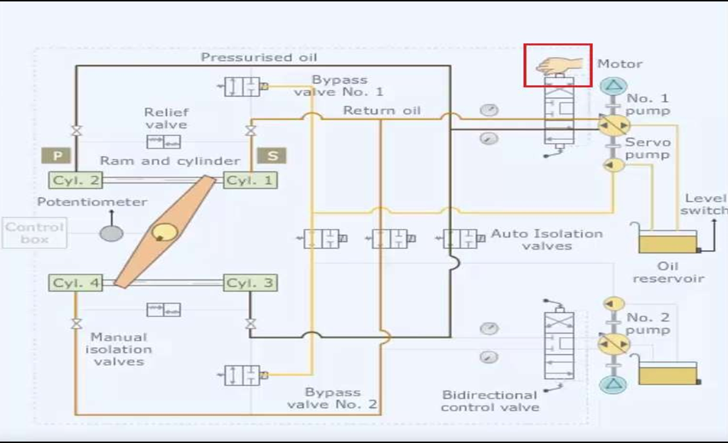
How safematic design is achieved in steering in case of Tankers of above 10000 GRT? Or Explain how automatic fail-safe arrangement is achieved in such system?
- Consider, during the operation, there is a damage in one of the pipes.
- The oil starts leaking and oil level starts dropping in the oil reservoir.
- The low-level alarm is raised.
- After the low-level alarm actuated, electrically operated isolating valves are closed and No.2 pump also started automatically.
- Now both systems will be running as two independent systems.
- If low-low alarm is activated in No.1 system reservoir, the leakage is confirmed in No.1 system, No.1 bypass valve will open.
- As there will be no pressure from servo pump, No.1 pump and No.1 system will be isolated. Only No.2 system will be in operation.
- Similarly, if low-low alarm is activated in No.2 system reservoir, the leakage is confirmed in No.2 system, No.2 bypass valve will open. No.2 pump and No.2 system will be isolated.
- Thus, the defective system is isolated and other system is in use
What is the function of the following in safematic system a) Oil level detectors (5) b) Automatic bypass / isolating valves, and (5) c) Relief valves?
Oil Level Detectors:
- Oil level detectors are fitted in the oil reservoir to sense the low-level alarm and low-low-level alarm.
- Consider there is a failure in No.1 pump line.
- If low-level alarm is actuated, it sends signals to close the isolation valves of the system and other pump is started automatically.
- Now No.1 pump & 2 pump will be separate systems.No.1 pump will handle No.1 & 2 cylinders/rams. No2 will handle No.3 & 4 cylinders/rams.
- When oil further drops, low-low-level alarm is actuated it sends signals to open the bypass valve.
- Thus, defective system No.1 is isolated and other system No.2 is in operation.
Automatic bypass / isolating valves:
- Under normal condition isolating valves are open and bypass valves are closed.
- When there is a leak in system and low-level alarm is actuated, the isolation valves are closed.
- This isolates the no.1 and no.2 system as two separate system.
- Further, when low-low-level alarm is actuated in No.1 oil reservoir, the bypass valve in No.1 will open.
- In this case No.2 pump will supply oil to No. 3 and 4 only. So only one set of rams will be in operation.
Relief Valve:
- After receiving signal from the bridge, the rudder is locked hydraulically at the ordered helm.
- External forces such as wave pressure etc. will tend to move the rudder from its position.
- Now the rudder experiences twisting force, i.e. wave trying to move the rudder and hydraulic force resisting it.
- If this twisting torque is excessive, the rudder stock may twist.
- To prevent such damage, relief valves are provided.
- When there is an excessive built up of pressure in the system, the relief valve lifts up releasing the pressure.
- This allows the rudder to give way from its locked position. But the pump stroke lever disturbed again due to set angle received from bridge, this causes pumping of oil and gets the rudder to the set angle.
Precautions prior starting a steering gear
- Check the hydraulic oil level in the tank. Insufficient hydraulic oil level will lead to poor performance of the system.
- However, alarms are provided to warn the operator.
- Check whether the manually operator isolation valves are in open position. If they are shut inadvertently it will affect the ram movement.
- Check the greasing and oil level. Insufficient lubrication will wear out the components.
- Check whether power supply is available for both the steering motor.
- Standby steering motor power supply should be available for emergencies.
- Check the amperage of the motor after starting the motor.
Advantages and disadvantages of: rotary vane steering over ram type
Advantages of rotary vane steering gear over ram type:
- Its weight is less
- It can be fitted without a rudder carrier; (a separate rudder carrier is not required. The rudder weight is taken by the thrust bearing in the unit)
- It is compact and saves space
- No transverse load on rudder bearings as the torque is directly transmitted to rudder stock
Disadvantages of rotary vane steering gear:
- Efficient sealing arrangement is difficult to achieve. It has a leakage path from high pressure to low pressure side
- It is limited to ships requiring low rudder torque, because high torque requirement leads to high pressure requirement
- Mechanical advantage is unity for all angles
How emergency steering is carried out in ram steering gear system. Or What action will you take in case of Tele-moter failure of steering gear?
- Consider, during the operation, the power supply fails in the control unit.
- In such an emergency, an alternative communication system is used to give the helm order to the steering compartment.
- The bidirectional control valve is actuated manually by using the levers.
- When the forward side lever is operated, the bidirectional control valve moves towards forward side.
- The ram in turn moves the rudder to the port side.
- When the desired rudder movement is achieved, the manual operator releases the lever and valve comes back to the initial position.
- The steering gear system is shut down when the ship reaches a port and berthed alongside.
- The steering pump motor is switched off. The control power supply at the bridge is switched off.
Rotary vane steering gear system
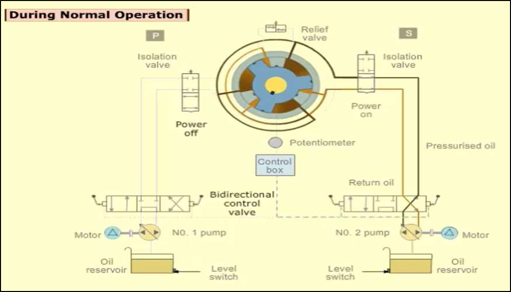
Working:
- There are two sets of hydraulic power packs comprising of hydraulic pumps and oil reservoir.
- Bi-Directional control valve changes the direction.
- Automatic isolation valves isolate the defective system in case of emergency.
- Bypass valves for each set of rams bypass the defective rams when isolated.
- Combined shock buffer relief valves maintain the system oil pressure within limits.
- The control box receives helm order from bridge and sends electric signals to directional control valve.
- The bidirectional control valve moves to the left (If port order) or right (if stbd order).Pressurised Hydraulic oil is supplied to the rotor and moves the rotor vanes.
- The rotor in turn moves the rudder stock.
- The oil is returned through the return side.
- Potentiometer senses the rudder stock position and sends a feed back to control box.
- Control box sends signal to bidirectional control valve and valve is pushed back to initial position, thereby locking the rudder position.
IMO requirements for testing of the steering gear units
- Tests should be carried out within 12 hours before each departure and satisfactory.
- Operation of main steering gear.
- Operation of auxiliary steering gear or use of the second pump which acts as an auxiliary.
- Operation of the Remote-Control system from the main bridge steering positions.
- Operation of steering gear using the emergency power supply.
- Check rudder angel indicator reading with respect to the actual rudder angle.
- The alarms fitted to the remote-control system.
- Steering gear power unit failure alarm.
- Steering gear header tank level
Different modes of steering gear controls provided on the bridge of a ship, explaining the significance of each system
Steering modes on bridge are follow-up mode, non-follow up mode and Auto.
Follow up mode:
- When the helm is moved away from midship position, a rudder command voltage starts the steering gear, causing the rudder to move.
- As it moves, an electrical feedback signal from the rudder stops any further movement once the desired angle of rudder is reached.
- Rudder remains in this position until the helm remains at the same angle.
- Thus, rudder follow-up the command given using the helm order.
Non-follow up:
- In NFU mode, the NFU controller when moved in one direction, the rudder will continue to move until the command is removed or the rudder limits reached.
- If the controller is returned to midships, the rudder will still remain at that angle, will not return to midships.
- Thus, the rudder does not follow up with the controller.
Auto mode:
- This is a automatic steering mode and steering is controlled by auto pilot.
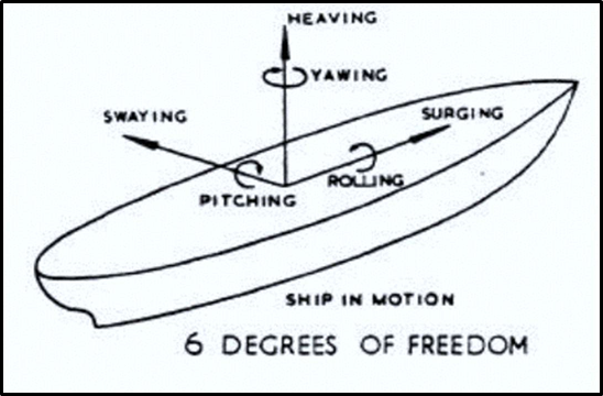
Six degrees of freedom of a ship? a) Tilting fin system b) Anti – rolling tanks.
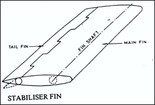
Tilting Fin System:
- Two fins system is one of the devices used on ships to resist rolling.
- The system requires a separate power supply and hence called active system.
- Two fins extend from the ship side at about bilge level.
- They are turned in opposite direction as the ship rolls.
- The forward motion of the ship creates a force on each fin and hence produces a moment opposing the roll.
- The fins are turned my electric motor.
- When the fin is turned down, the water exerts an upward force. When the fin is turned up, the water exerts a downward force.
- Fins are rectangular and turn about 20°. Most fins are retractable.
Active Anti-Rolling Tanks:
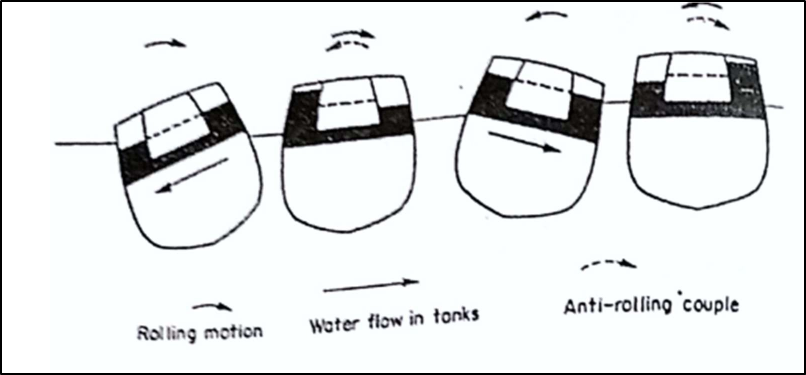
- The tanks are above the centre of gravity.
- The tanks are connected by lower limb like a ‘U’ tube.
- The air duct contains the valves operated by a roll sensing device or accelerometer.
- The accelerometer senses the rolling motions and sends signals to pump.
- The pump in turn pumps the water to the other side to resist rolling.
- Instead of accelerometer, a gyroscopic sensing system may also be used.
Anti-heeling system:
- Anti-heeling system is incorporated to compensate for the list of the ship during cargo operations.
- This allows the vessels to have continues loading and unloading cargo operation without stopping in between for list correction.
- This saves considerable amount time on the port.
- In this system, ballast tanks are internally connected to each other by means of pipe lines, automatic valves and control systems.
- When the ship heels to any of the sides, the heeling sensor sends the signal for change of ships angle with respect to the ship’s upright position to the master control panel.
- This change in heeling angle is compensated by methods of auto transferring the water from the heeled side to the other side of the ship, making the vessel upright.
- The transferring system could be either pneumatic or water pump system.
Bilge keel and passive anti-rolling tanks
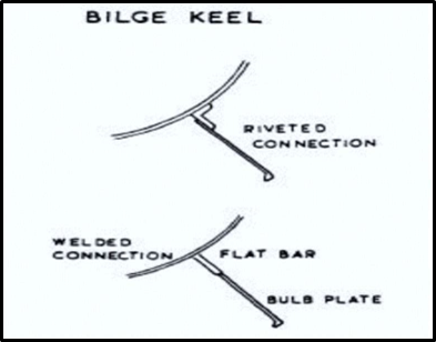
- Bilge keels are fitted at the turn of the bilge to resist rolling; they also improve slightly the steering qualities of the vessel.
- They usually extend over the midship one-third or half length.
- They should be attached to a continuous flat bar which may be welded to the shell plating.
- The ends are to be gradually tapered and should not end on an un– stiffened panel.
- Today, in many vessels, stabilizers are being fined in lieu of bilge keels.
Passive Anti-Rolling Tanks
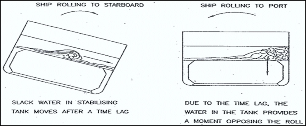
- Active anti-rolling tanks uses pumps or other machinery to pump the water from one tank to the other.
- Whereas in passive anti-rolling tanks, the movement of water is natural but delayed.
- Thus, when ship is finishing its roll and about to turn, the still moving water will oppose the return roll.
- The water mass thus acts against the roll at each ship movement.
- The delayed movement of water is made possible by baffles or other suitable means.