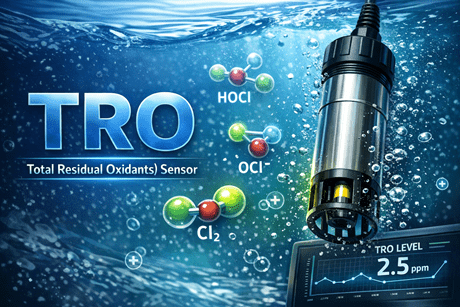
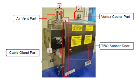
TRO Sensor
Ballasting TRO Concentration Alarm/Shutdown
TRO_ _ _BHL [TRO-_ _ _] HIGH/LOW ALARM IN BAL
SHD_TRO_ _ _ [SHD_TRO_ _ _ ] SHDN BY TRO VALUE
Abnormal TRO value
Take measures referring to the following instructions.
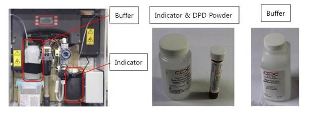
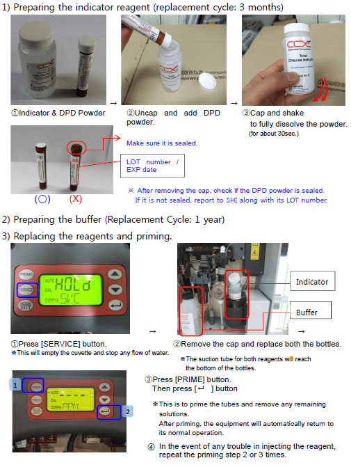
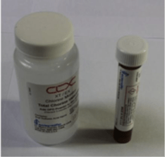
1. Check the amount, color, expiration and replacement cycle of the TRO indicator reagent and replace it if needed.
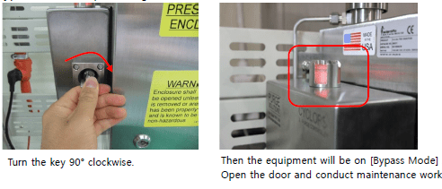
– For CLX-EX (anti-explosion type), be sure to switch to [Bypass mode] prior to replacing the reagent.
1) Replacement cycle:
Buffer: 1year Indicator: 3 months(When kept in the cooling chamber below 25.)
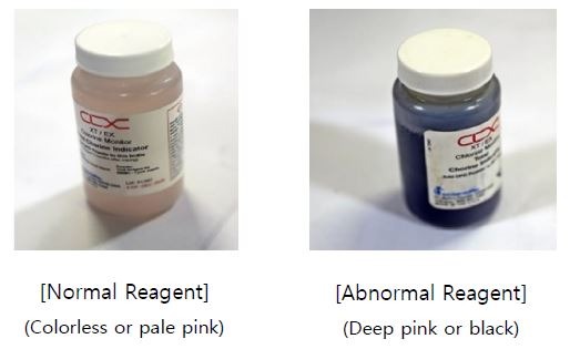
2) Regardless of the replacement cycle, if the indicator reagent is badly discoloured due to the malfunctioning of the cooling unit, replace the reagent as well as the cooling unit.
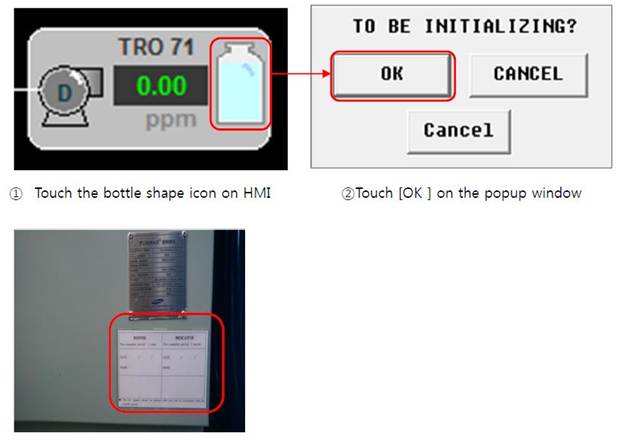
3) After replacing reagents (Buffer and Indicator), initialize the replacement cycle setting.
Reagent Replacement
For CLX-EX (Anti-explosion type), be sure to switch to [Bypass mode] prior to replacing the reagent.
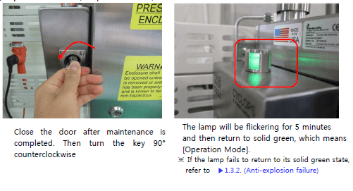
Bypass Mode Conversion (CLX-EX Only)
Indicator Lamp
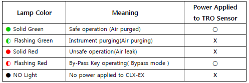
Bypass Mode(Lamp : Flashing Red)
Operation Mode(Lamp : Solid Green)
In case the reagent is degraded earlier than the replacement cycle, you need to
check the condition of the cooling unit.
>> High temperature in the cooling chamber may cause degradation in reagents.
1 Inject warm water above 25. and check if the cooling fan is normally operating.
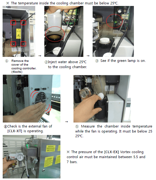
2) If there is any trouble in operating the cooling unit, replace it.
3) After replacing the cooling unit, exchange its reagents as well.
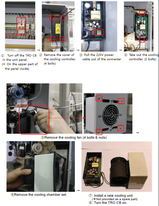
Cooling Unit Disassembling
1. CLX-XT
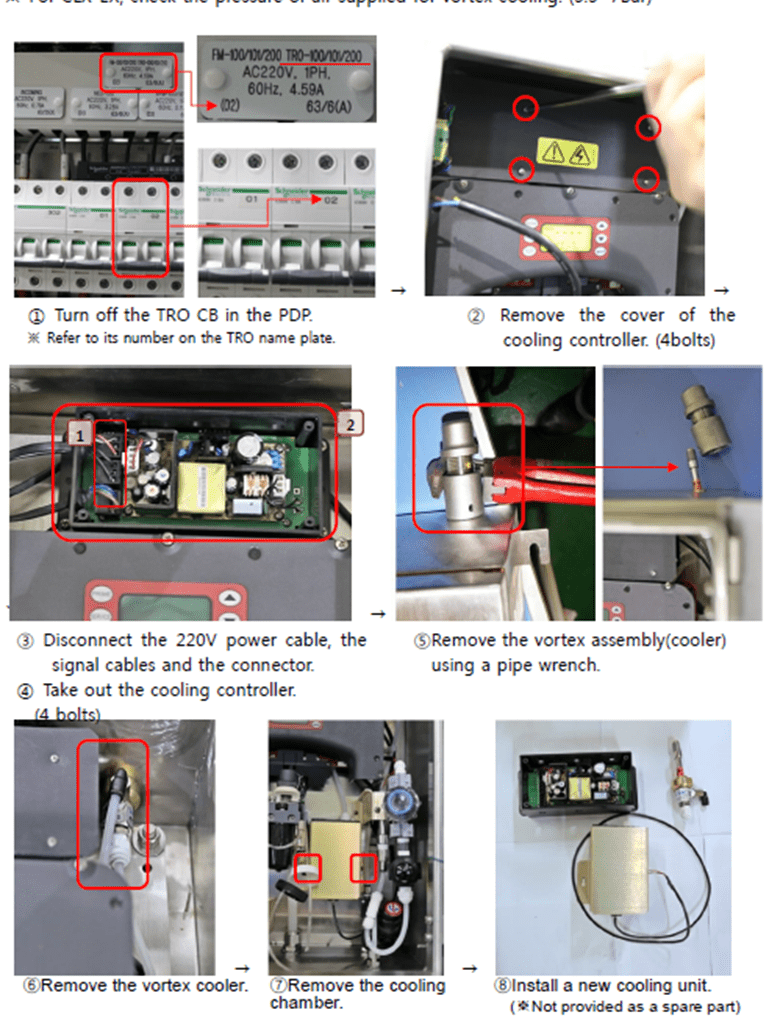
Cooling Unit Disassembling
2. CLX-EX
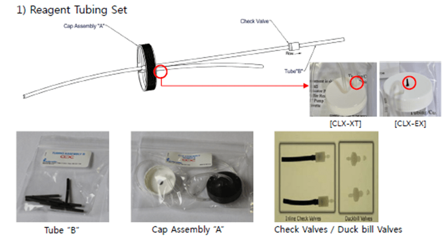
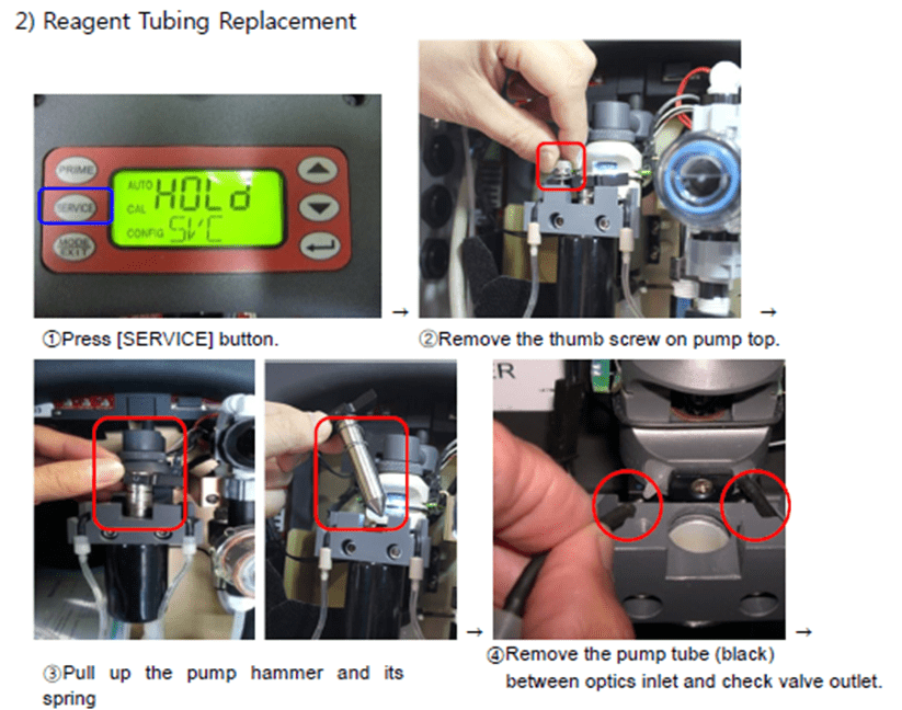
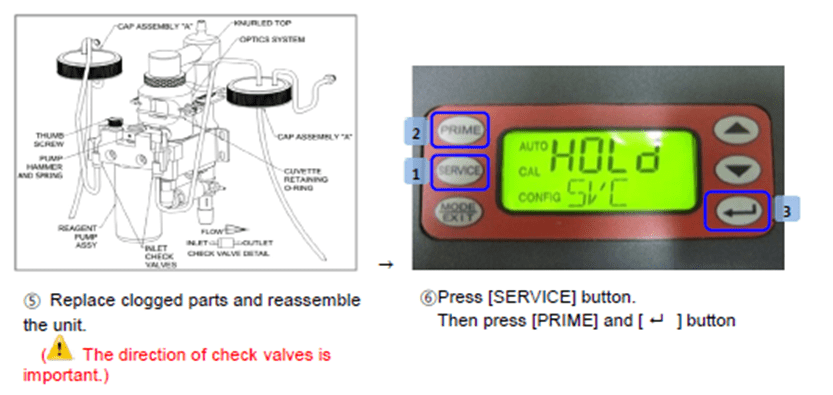
3. Flush off the reagent tubes and check valve lines.
. After a long-term standby, check valves can be blocked due to the solidification of the remaining reagent. In this case, manually prime the lines with a flushing kit.
1) How to use the flushing kit for manual priming.
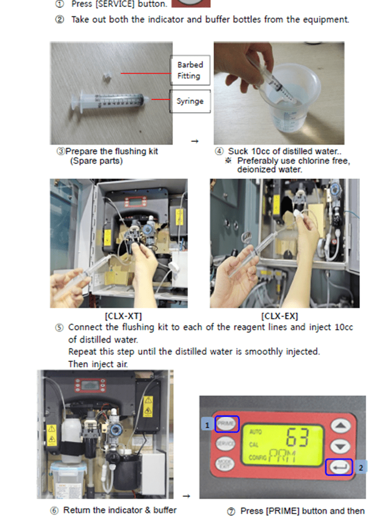
2) When tubes or check valves are clogged, wash them before priming.
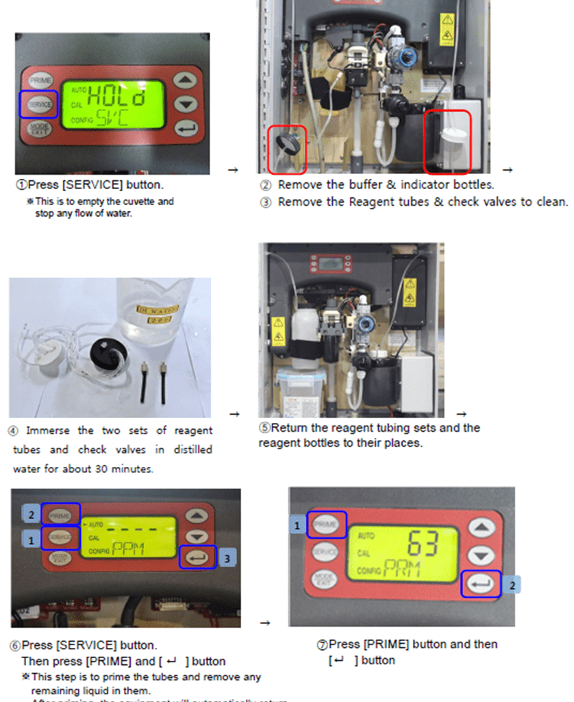
4. In the event of any leak or trouble in flushing, examine if the check valves and tubes are not clogged. Check their condition and replace them if needed.
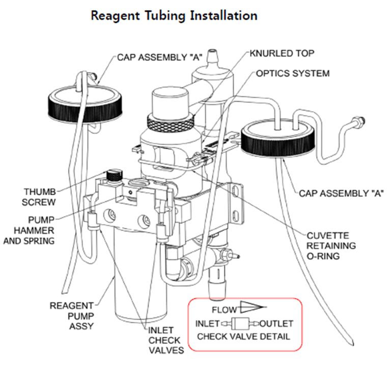
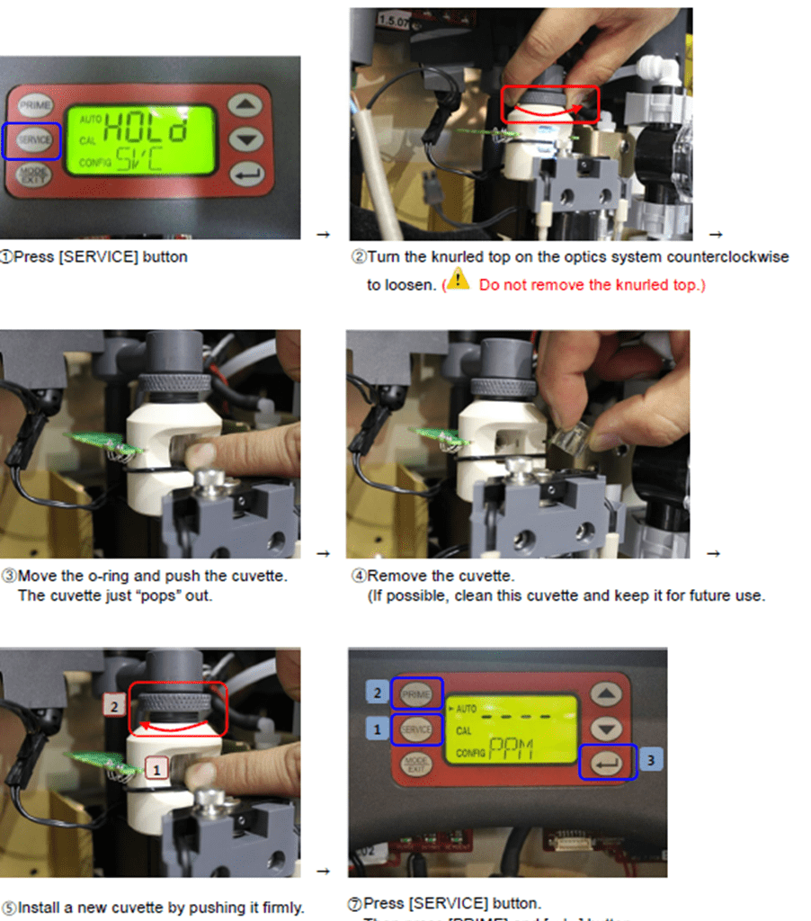
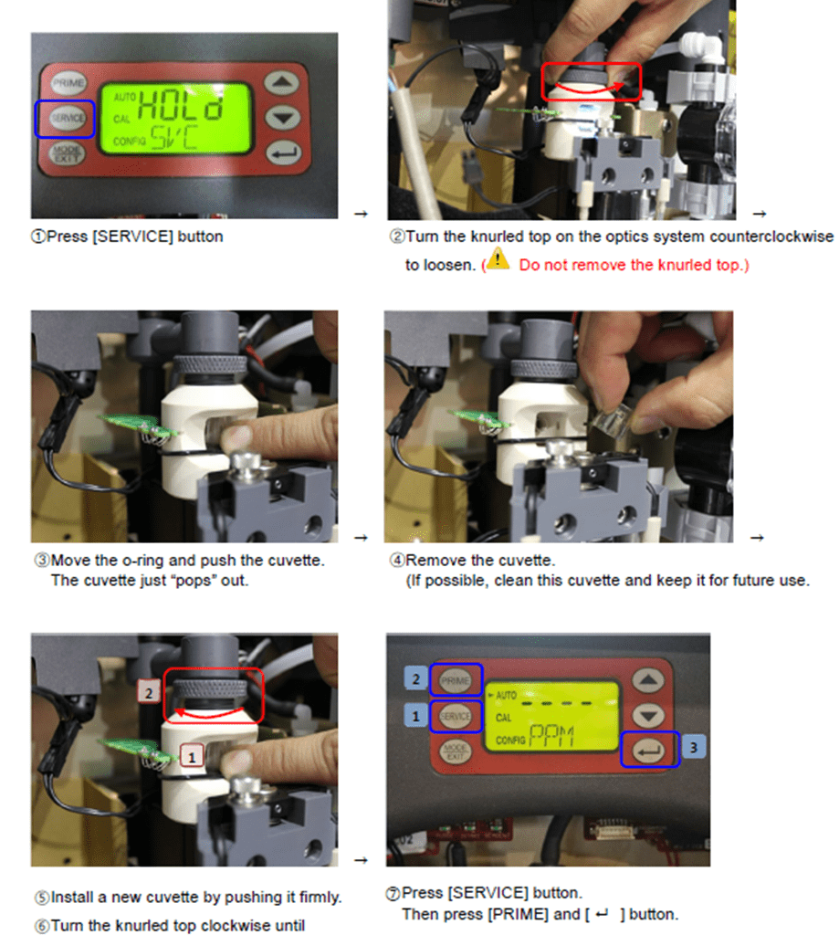
5. Check for any contamination on the cuvette. Clean or replace it as needed. If the cuvette appears badly soiled or discolored, replace it following the steps below.
No Sampling water / Low Flowrate
. For CLX-Ex (anti-explosion type), maintenance is done on [Bypass mode].
1. If the ballast tank is empty, generate back pressure.
. An empty ballasting tank generates negative pressure on the TRO suction point, which will cause failure of sampling water suction.
1) Gradually close the valve on the main line, so that back pressure is generated at the end of the TRO suction point.
2) Restart operation and check if the cuvette is provided with water.
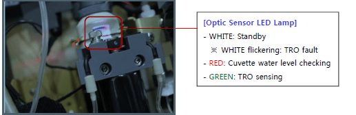
3) Make sure the red lamp of the optic sensor is turned on.
4) On the HMI, [Low Water] notice will be removed.
. In case the notice is not available on the HMI, check the display of the local TRO unit to see if [WATER/SLOW] signal has normally disappeared.
2. If the alarm is not released, check the condition of the sampling pump.
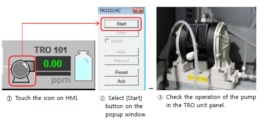
1) On the HMI, touch [Sampling Pump] icon to check the actual operation of the pump.
2) Check the air pressure to make sure air is normally supplied. (Air supply from shipside)
3) Using the air regulator, control the pressure between 2.5 and 4 bars for the sampling pump.

4) After controlling the air pressure, set the flowrate.
5) If the sampling pump is out or order despite normal air supply, it is required to repair or replace the pump or its sol valves.
3. Check the condition of the T strainer and water regulator inside the TRO sensor. Clean or replace them as needed.
While removing a T-strainer, remaining water may come out by pressure. For water can cause trouble in a TRO sensor, be careful not to spill any water into the equipment.
1) Check the T-strainer kit.

2) Check the condition of the water regulator kit after disassembling it.
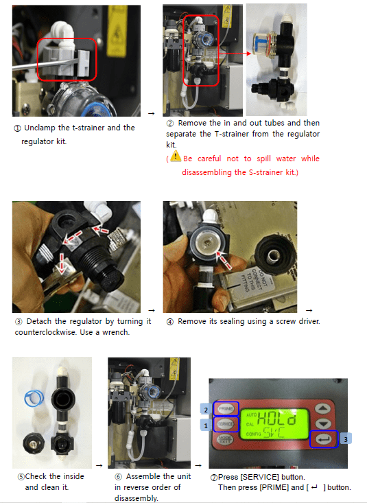
3) Set the flowrate of the TRO sensor.
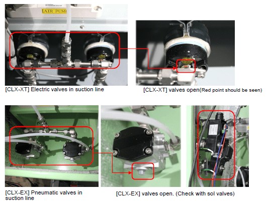
4. Check if the valves on the TRO suction line are normally operating.
1) On the HMI, touch [Valve] icon on the suction line and select [Open] button on the popup window.
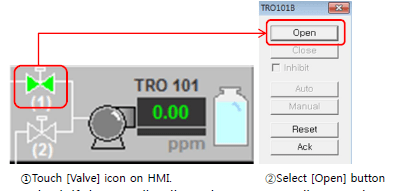
2) Check if the sampling line valves are normally operating.
3) If any trouble is found, repair or replace the valve.
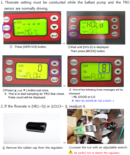
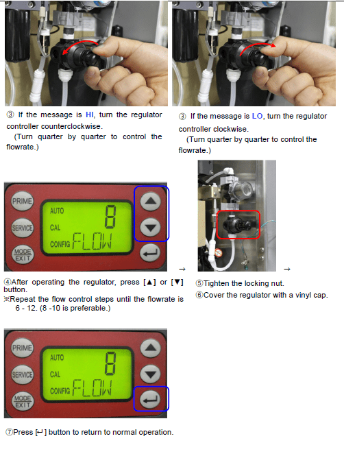
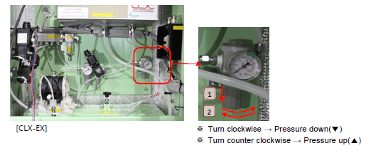
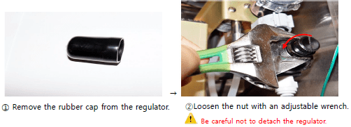
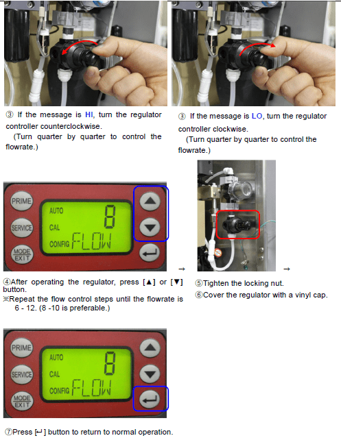
TRO Sensor Flowrate Setting
- In one of the following cases, readjust the flowrate.
1) Supply air pressure for the sampling pump has been changed on the TRO sensor unit panel.
2) A needle valve on the bypass line has had any change in setting.
3) The regulator of the TRO sensor has been repaired or its settings have been changed.
1. Flowrate setting must be conducted while the ballast pump and the TRO sensor are normally driving.
Abnormal flow distribution due to flow control valve error in electrolysis unit
This is applied only to hulls that have separate NaOCl lines for PORT and STBO.
(I.e. the electrolysis unit provides NaOCl separately to PORT and STBO.)
1. Check the operation of the flow control valves.
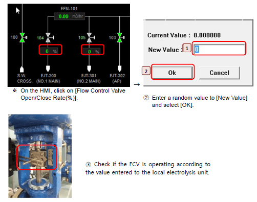
2. When any trouble is found, repair or replace the flowrate control valve.
TRO Concentration in Deballasting > 0.1ppm Alarm > 0.2ppm Shutdown
TRO_ _ _DH [TRO-_ _ _] ALARM IN DEBAL
[TRO_ _DH] HIGH AT DEBALLASTING
SHD_TRO_ _ _ [SHD_TRO_ _ _ ] SHDN BY TRO VALUE
Abnormal Data on TRO Sensor
1. Check the amount, color, replacement cycle of the TRO indicator reagent. Replace the reagent if necessary.
2. If the reagent is discolored earlier than expected by the replacement cycle, examine the cooling unit.
3. Flush off the reagent tubes and the check valve lines.
4. Check if any tubes or valves are clogged, replace them if necessary.
5. Check cuvette condition. Clean or replace the cuvette if it is contaminated.
Sampling Water NO / Low Flow
1. In the event of [Ballast Tank Empty], control the main line valves.
2. Check sampling pump condition.
3. Check the T-strainer and the regulator. Clean or replace them if necessary.
Trouble in Neutralization Unit
1. Check valve arrangement in the neutralization unit.
Valve arrangement is based on the flow diagram and neutralization unit P&ID of the Operating Manual, so that the neutralizer (sodium thiosulfate pentahydrate) can be injected to where deballasting takes place.
2. If the HMI gives an alarm related to neutralization, or the neutralizer pump shows an error code on its LCD display, take neutralization troubleshooting manual. .
3. Check the amount of the neutralizer used.
TRO Sensor System Fault Shutdown
SFT_TRO_ _ _ [ELE] SHUTDOWN BY TRO-100 SENSOR FAULT
[ELE] SHDN BY TRO-100 SENSOR FAULT
[TRO-102] SHDN BY TRO FAULT[ELE] SHDN BY TRO-110 FAULT
[CLX-XT(Non EX)] TRO Sensor fault
1. Check if the LCD display on the TRO sensor is on.
2-1. If the LCD display on the TRO sensor is off;
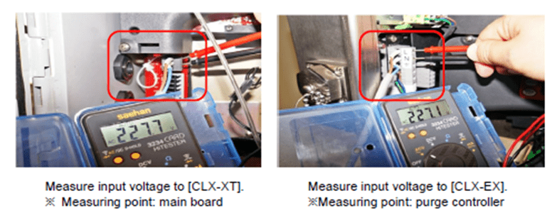
1) Measure input voltage to the TRO sensor, to see if power supply is normal.
(Normal voltage: AC 220V – 240V)
2) If the voltage is not in the normal range, examine the power supply line. Check if the PDP panel CB is on, reviewing the cable connection.
3) If the voltage is in the normal range, it is necessary to replace the board. .
If the LCD display on the TRO sensor is on;
1) Referring to the ECD(Electric Connection Diagram), check if the CPU card lamps are flickering. (In normal condition, both TX and RX are flickering.)
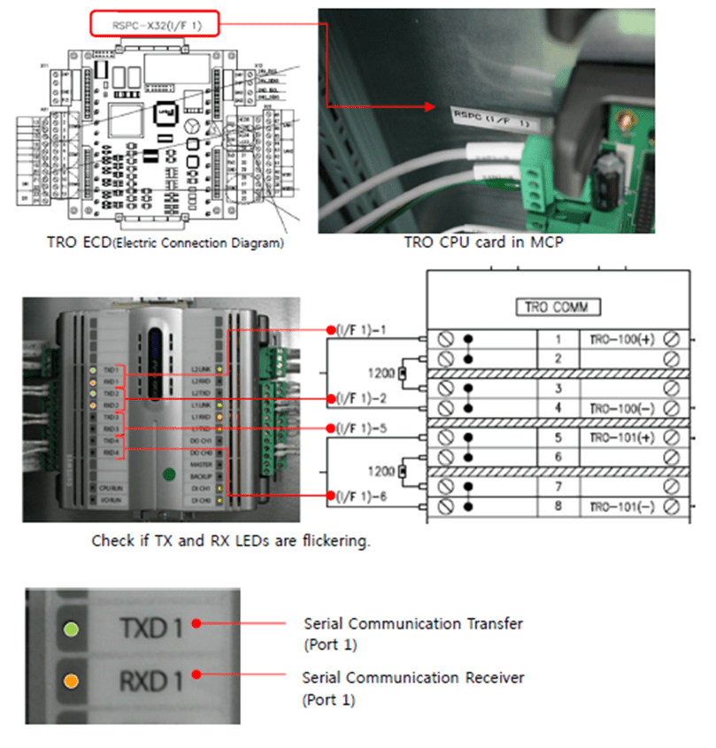
2) In the case when neither of the CPU cards is flickering or just the RX lamp is
flickering, it is regarded as a CPU card error. Examine the CPU card.
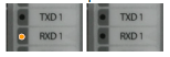

3) If just the TX lamp is flickering, it is regarded as a communication error,
which means no feedback is made for the data request. Check the following.
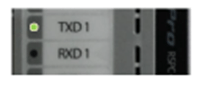
- Cable connection between TRO and MCP.
- Communication settings for RS 485.
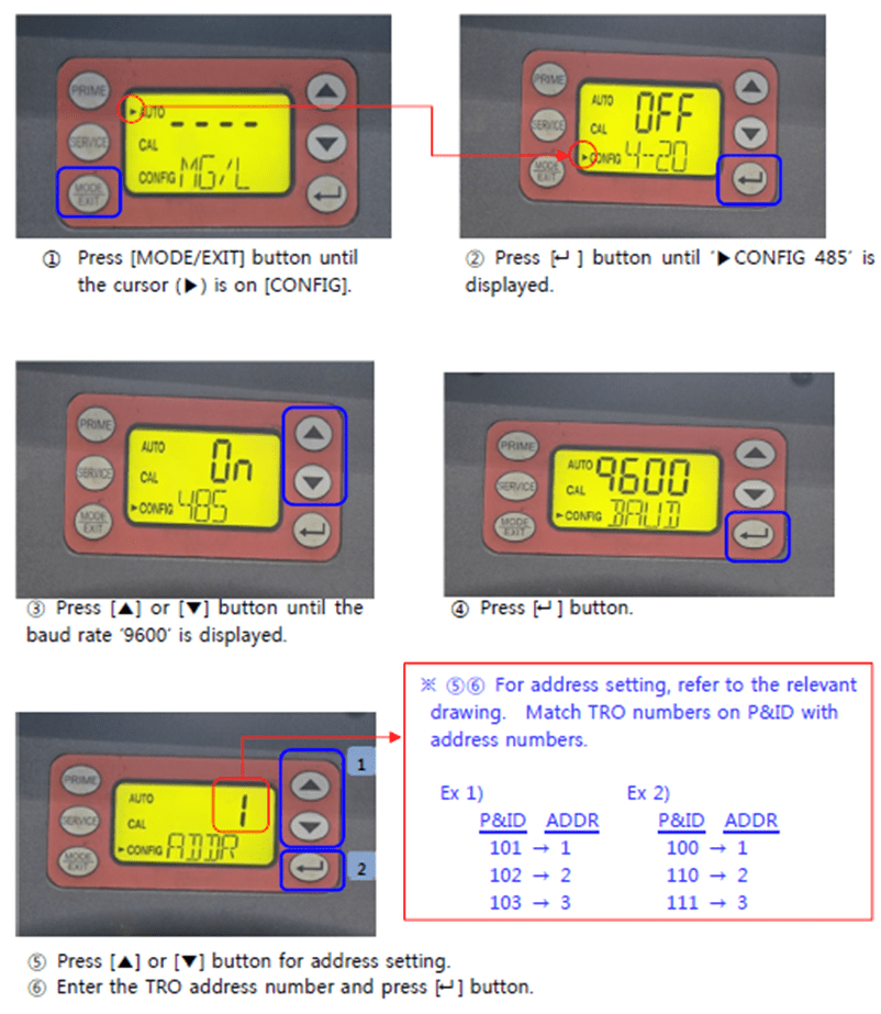
RS-485 Port Configuration
4) If the alarm is not released even after troubleshooting as above, it is required to replace the main board.
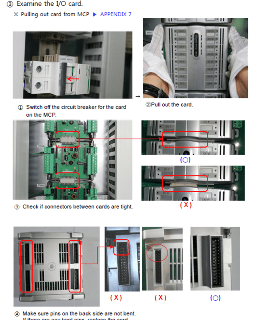
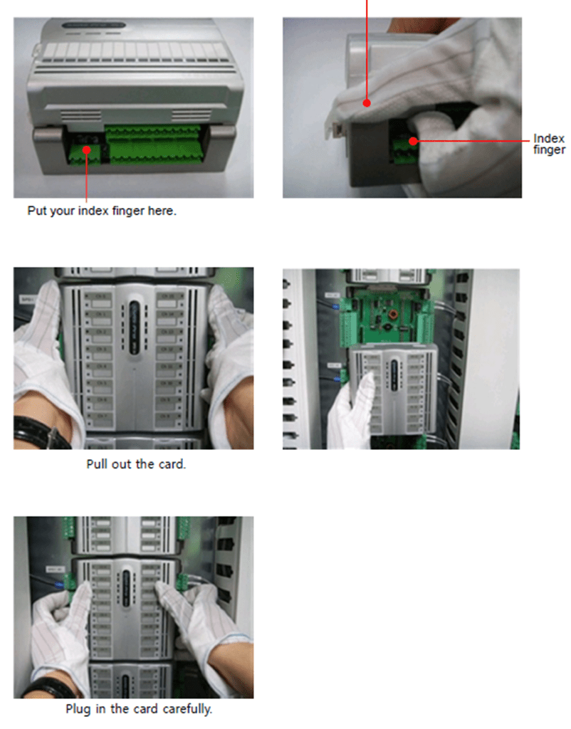
MCP Card Disassebling
1. Pull out the card from the MCP
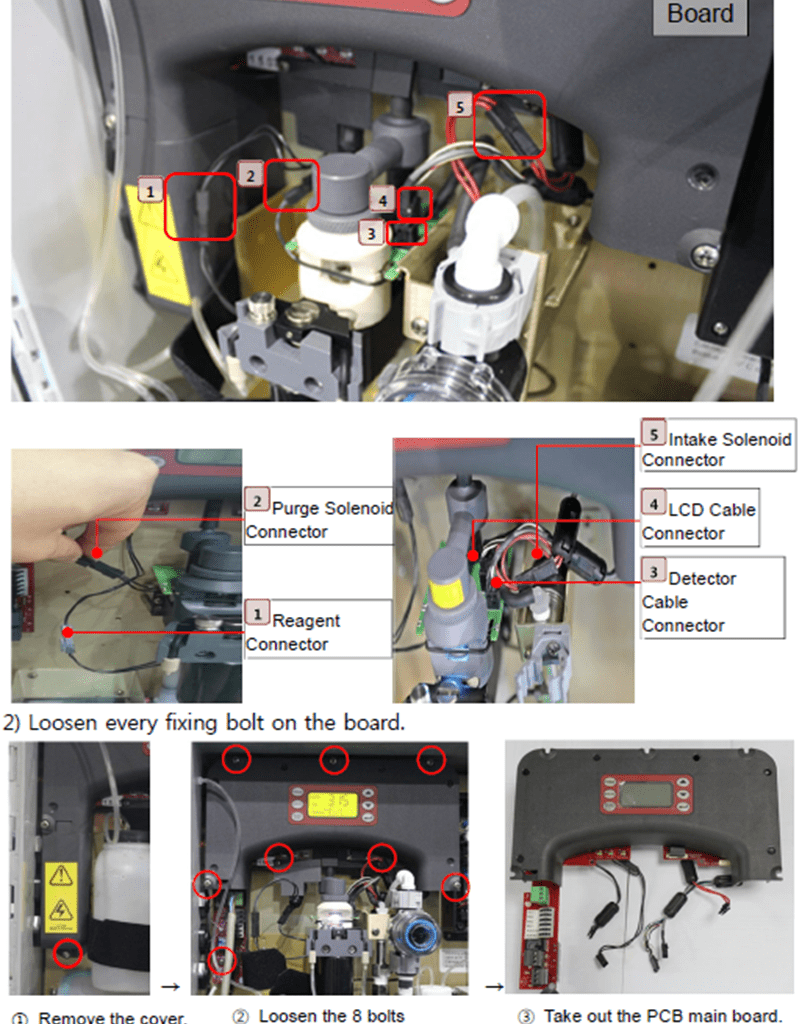
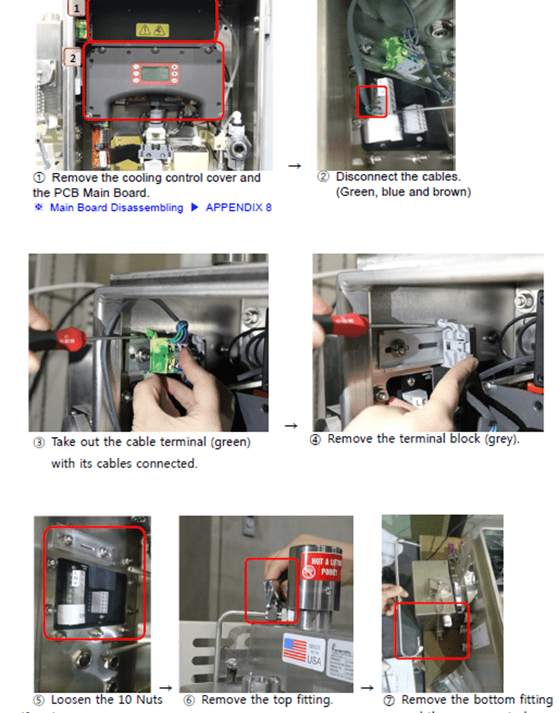
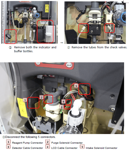
PCB Main Board Disassembling
1) Pull out the 5 connectors between the optic unit and the PCB main board.
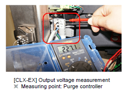
CLX-EX TRO Sensor Fault
1. Check the purge controller lamp as follows.
- Purge Controller Lamp : ● No light
1) Measure input voltage to check if power supply is normal. (Normal voltage: AC 220V)
2) If power supply is judged normal, the fault is regarded as an error in the purge
controller. Replace the purge controller.
– Purge Controller Lamp : ◐ Flashing Green or ● Red
1) Check if the TRO sensor is on its operating mode.

2) Control the air regulator of the TRO sensor so that the air pressure can be maintained within 5.5 – 7 bars.
3) Check for any air leak from the TRO sensor.

6) If the [TRO Sensor Fault] state still continues after troubleshooting as above, it is required to replace the purge controller
Purge Controller Disassembling
- Purge Controller Lamp: ● Green Solid
Check if the TRO sensor display is on.
If the display is off;

Measure the output voltage of the purge controller. (Normal voltage: AC220V~240V)
– If the voltage is out of the normal range, replace the purge controller.
– If the voltage is in the normal range, it is required to replace the main board.
If the display is on;
- Check the CPU card.
- Check cable connection between TRO and MCP.
- Check the communication settings of RS 485.
- Check the I/O cards.
Buffer Expiration Alarm
TRO_ _ _BF [TRO] REPLACE BUFFER
Buffer expired (Validity: 1 year)
1. Replace the buffer and conduct priming. .
For CLX-EX, convert to [Bypass Mode] before replacing the buffer.
Indicator Expiration Alarm
TRO_ _ _IND [TRO] REPLACE INDICATOR
Indicator expired (Validity: 3 months)
Exchange the indicator and conduct priming.
. For CLX-EX, (anti-explosion type), be sure to switch to [Bypass mode] prior to replacing the reagent.
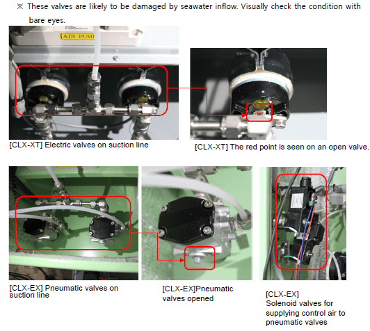
TRO Valve Order Fail Alarm(Electric Valves Only)
TAV_ _ _ _FO [TRO] SOL VLV ORDER FAIL
Failure of sampling valves in TRO sensor unit panel
1. Check the cable connection of the sampling valves.
2. Check if the TRO remote valve is normally operating.
In the event of any trouble in the valve, repair or replace it. . Erosion due to seawater inflow may have caused such trouble. Visually check for it.
TRO System Abnormal
TRO_ _ _XA [TRO-_ _ _] ABNR
Local TRO LCD : WATR or SLOW
(Water intake failure or too slow flowrate)
1. Check concentration data on the TRO sensor
Local TRO LCD : FAST
(Too fast intake water flowrate)
. In one of the following cases, readjust the flowrate.
1) Supply air pressure for the sampling pump has been changed on the TRO sensor unit panel.
2) A needle valve on the bypass line has had any change in setting.
3) The regulator of the TRO sensor has been repaired or its settings have been changed.
1. Flowrate setting must be conducted while the ballast pump and the TRO sensor are normally driving.
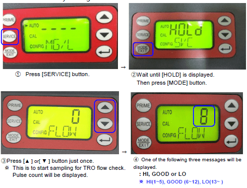
2. If the flowrate is [HI(1~5)] or [LO(13~ )], readjust it.
Local TRO LCD : GLAS (Dirty cuvette)
Check for any contamination on the cuvette. Clean or replace it as needed. If the cuvette appears badly soiled or discolored, replace it following the steps below.
Local TRO LCD : PURG or NPRG or PSOL
(Sampling cuvette purge failure, too slow purge or purge solenoid trouble)
1. Check if the purge solenoid valve is normally operating.
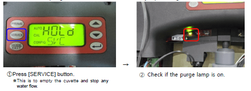
If the purge lamp is turned on; (I.e. the purge solenoid valve is normally operating.)
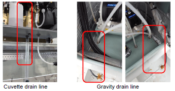
1) Check if sample water in the cuvette is normally being drained through the TRO sensor gravity line.
-If the drain apparently has any trouble, check if the cuvette drain line is clogged. If necessary, flush it off.
-Or otherwise, check if the gravity drain line is clogged or has any reverse flow in it.
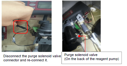
If the purge lamp is off;
(i.e. the purge solenoid valve is in abnormal condition.)
1) Disconnect the connector of the purge solenoid valve and connect it again.
3. If trouble continues after troubleshooting actions as above, it is required to
replace the optic sensor.
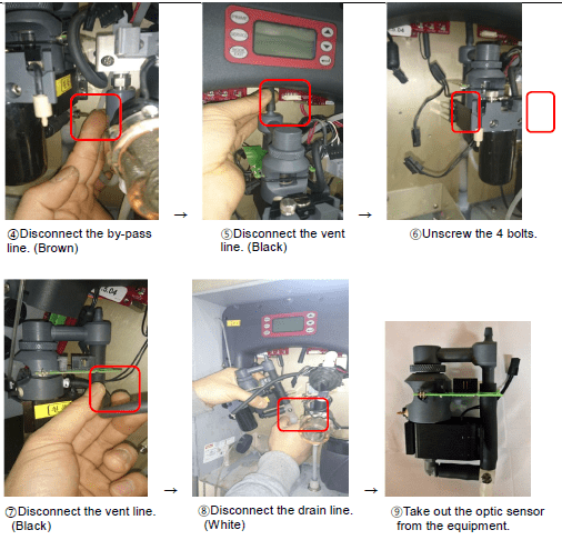
Disassembling Optic Sensor
Local TRO LCD : ISOL
(Intake solenoid trouble)
- Check if the intake solenoid valve is normally operating.
- If the intake solenoid lamp is not turned on, try reconnecting its connector.
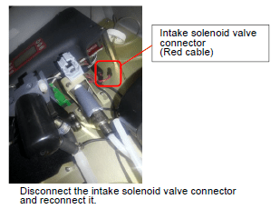
- If the intake lamp is turned on, check if sample water is normally inflowing through the drain line.
- If trouble continues after troubleshooting actions as above , it is required to replace the intake solenoid valve. .
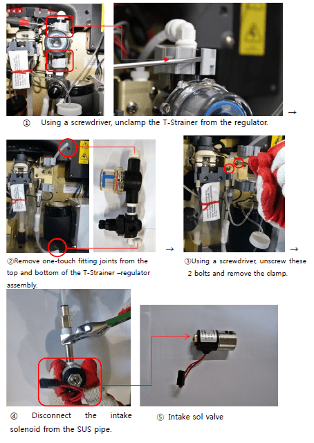
Intake Sol. Valve Disassebling
Local TRO LCD : POST
Local TRO LCD : -GRN0, GRN1, GRN2(Visible lamp trouble) -WTR0, WTR1, WTR2(IR lamp trouble)
Local TRO LCD : -SOL0, SOL1, SOL2, SOL3(Solenoid trouble)
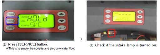
1. Reset the TRO MCCB in the local electrolyzing unit PDP. (Off . On)
2. Press [SERVICE] button on the local TRO sensor.
3. Disconnect the 5 connectors and reconnect them.

4. If trouble continues after troubleshooting actions as above, it is required to replace the board or the optic sensor.
Local TRO LCD :
-0x00001 0x00002 0x00004 0x00008 0x00010
0x00020 0x00040 0x00080 0x00100 0x00200
1. Simultaneously press both [ . ] and [ • ] buttons for factory initialization.

2. Set RS-485 communications.
3 If trouble continues after troubleshooting actions as above, it is required to update the software or replace the PCB main board.