Arrangements on stern tube lubricating system and the arrangements for mitigating the oil leakage into sea
Purpose:
- Special seals are fitted at the ends of the tail shaft.
- They are arranged to prevent the entry of sea water and the loss of lubricating oil from the stern bearing.
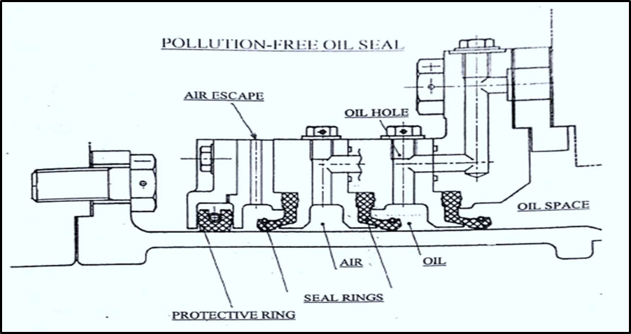
- Advanced pollution free seal ensures sea water and oil side are isolated by air chamber.
- If any leakage of oil or sea water occurs into the air chamber, it is automatically collected in the drain collection unit.
Arrangement
- The complete system comprises of air control unit, lube oil drain tank, lube oil pump unit and associated piping.
- Oil is contained within the simplex seal by the seal rings.
- The elastic lip of seal rings grips the rubbing surface provided by the chrome steel liners on the shaft.
- Friction produces heat which will result hardening and loss of elasticity of the rubber.
- Oil circulation ensures that the seals remain at a lower temperature.
Adverse effects of the after-end seal leakage to the propeller shafting
- When water or oil leaks through the after-end seal, it can increase the hydrodynamic drag on the propeller.
- This extra resistance can reduce the ship’s speed and fuel efficiency, resulting in increased operating costs.
- The presence of seawater can lead to corrosion of the propeller shaft, bearings, and other components in the aft section of the vessel.
- This can result in increased maintenance and repair costs.
- Furthermore, the abrasive nature of seawater can accelerate wear and tear on components, reducing their service life.
- If oil leaks from the after-end seal, it can deplete the lubrication supply in the stern tube bearing, potentially leading to increased friction and overheating.
- This can cause bearing damage and, in severe cases, result in catastrophic failure.
- In the case of oil leaks, environmental pollution is a significant concern.
- The integrity of the propeller shafting system is crucial for the ship’s overall reliability.
- After end seal leakage can compromise this integrity, potentially leading to costly breakdowns or delays in operations
- As the propeller operates in a less than ideal environment due to the presence of water or oil, it can experience cavitation and increased vibration, potentially leading to damage to the propeller and shaft.
Differences between fixed pitch propeller and a controllable pitch propeller
| Aspect | Fixed Pitch Propeller | Variable Pitch Propeller |
| Blade Angle Adjustment | Blade angle is fixed and cannot be adjusted during operation. | Blade angle can be adjusted to optimize performance as needed. |
| Efficiency | Generally, less efficient as they are set for a specific speed and load condition. | More efficient as they can be adjusted to match the engine’s power output and operating conditions. |
| Thrust Control | Limited thrust control, typically requiring engine RPM adjustment for power changes. | Allows precise thrust control without altering engine RPM. |
| Manoeuvrability | Limited manoeuvrability and less responsive to changes in load or conditions. | Provides better manoeuvrability and responsiveness, making them ideal for vessels that require frequent speed and load adjustments. |
| Reverse Thrust | Typically, doesn’t offer reverse thrust capabilities. | Can be adjusted to provide reverse thrust for deceleration and manoeuvring in reverse. |
| Noise and Vibration | Can produce more noise and vibration as RPM changes are required for power adjustments. | Can be operated at lower RPMs, reducing noise and vibration, |
| especially during low-power conditions. | ||
| Weight and Complexity | Simpler design, lighter weight, and lower maintenance requirements. | More complex, heavier, and requiring additional components like control systems. |
| Maintenance | Requires less maintenance due to the fixed nature of the blades. | Requires regular maintenance to ensure proper operation of the pitch control system. |
| Cost | Typically, less expensive to manufacture and maintain. | More expensive due to the added complexity and components. |
| Safety | Less safe in the event of engine failure, as there is no feathering option to reduce drag. | Safer in case of engine failure as the blades can be feathered to reduce drag and improve glide performance. |
Advantages and disadvantages of controllable pitch propulsion
Advantages:
- A shaft generator can be driven at constant speed while allowing at the same time a change in ship speed through the propeller
- Regular and frequent manoeuvring in and out of port is made easier with unidirectional and constant speed engine.
- CPP can be adjusted to match the ship’s speed and load, optimizing efficiency and reducing fuel consumption.
- The ability to fine-tune the pitch can help reduce vibration and noise, making the vessel more comfortable for passengers and crew.
- Ships can minimize cavitation, which can damage the propeller and affect efficiency. This is especially important for high-speed vessels.
- Can be adjusted to maintain optimal propeller loading in rough seas, improving vessel stability and reducing the risk of slamming or propeller damage.
Disadvantages:
- Head room is less since a medium speed, trunk piston engine is employed. Hence, it is mostly suitable for ferries
- Complicated propeller shaft and control system for propeller blades.
- Oil / water interface at propeller blade roots increase chances of pollution.
- More expensive to manufacture, install, and maintain than fixed-pitch propellers.
- Frequent and comprehensive maintenance required to ensure reliable operation.
- The components of a CPP system can be heavy and take up space, affecting the ship’s weight distribution and overall design.
- The hydraulic or electrical systems required to control the propeller pitch can result in energy losses and add to operational costs.
- Ship operators and maintenance crews need specialized training to operate and maintain CPP systems effectively.
Operation of a controllable pitch propeller
Controllable Pitch Propeller:
- In this type of propeller, it is possible to alter the pitch.
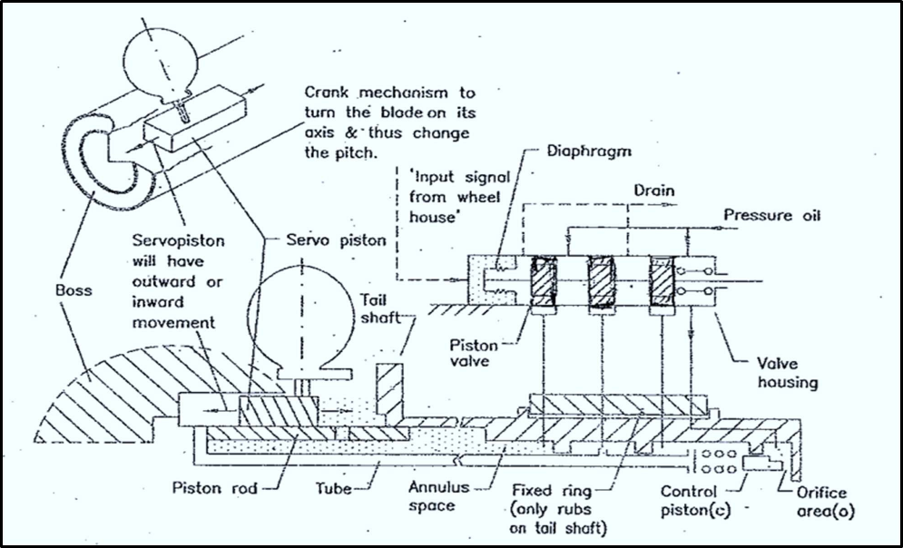
- Change in pitch is effected by rotating the blade about its vertical axis.
- This movement is carried out by hydraulic or mechanical means.
Working:
- The input fluid signal acts on the diaphragm in the valve housing and directs pressure oil via one piston valve through the tube to one side of servo piston.
- Movement of the servo piston, through a crank, rotates blades and varies pitch.
- Orifice area either increases or decreases, depending on the movement of servo piston, as servo piston is attached to the tube which in turn moves the control piston.
- Oil pressure under the piston valve is controlled by movement of servo piston.
- This acts as feedback restoring signal and thus bringing the piston valve back to neutral position after initial disturbance.
What is meant by keyed & keyless propeller mounting? What is rope guard and why it is fitted?Two methods of keyless propeller mounting
These are the methods of mounting the propeller to the tail shaft.
Keyed mounting
- The aft end of the propeller shaft is tapered, and keyway is milled in the taper portion.
- The key is accommodated in the bore of the hub.
- The propeller hub taper and shaft taper are accurately machined.
- When the propeller nut is tightened, the hub is forced on to shaft a few mm. to give a good interference fit.
Keyless mounting
- The keyless propeller has no key.
- This design eliminates the defects that could occur due to keyway.
- When propeller is fitted on to taper of the shaft, the friction between the surfaces is enough to prevent slip.
- The tightening of propeller or push up is done using hydraulic devices and carefully controlled
- Keyless mounting is forced on to the tail shaft by dry push (pilgrim nut method) or wet type (SKF method).
Rope Guard:
- The rope guard is fitted between the stern tube and the propeller.
- It consists of two half rings with blades bolted to them.
- Typically attached by means of welding or bolted with locking wires in place.
- The purpose is to protect the propeller from being damaged in the case that a rope is caught in it.
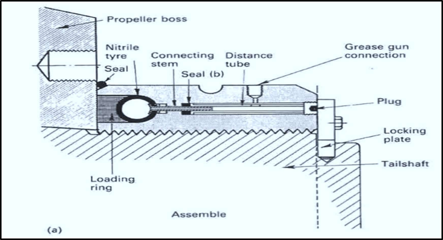
Pilgrim nut method:

- It has an internal nitrile rubber tube.
- When it is inflated hydraulically, it forces a steel loading ring against the hub.
- The propeller is positioned and initially jacked on to the shaft taper.
- The pilgrim nut is used to apply an initial loading of about 65-70 bar pressure. A reference obtained.
- The pilgrim nut is nipped up in place in flush with boss.
- For removal of propeller, the pilgrim nut is opened and reversed.
- A withdrawal plate and studs are used.
- Wooden blocks are inserted between boss and nut to safeguard any violent movement at release.
The SKF system:
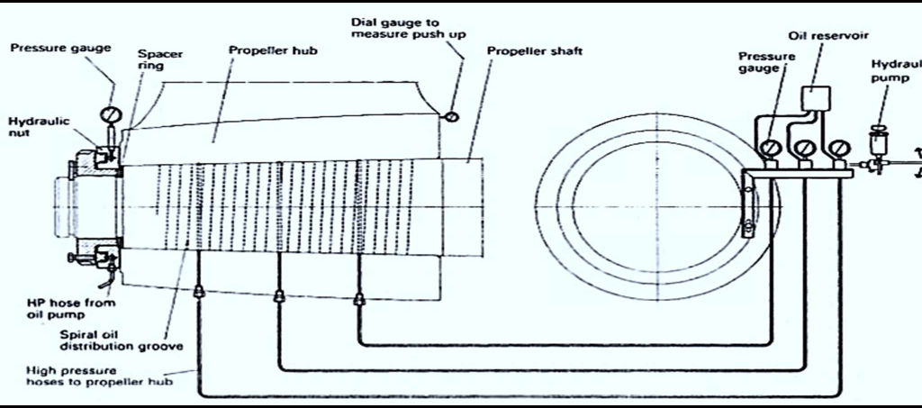
- The propeller bore has machined grooves, helically or axially and circumferentially.
- A hydraulic ring jack is arranged between shaft nut and aft face of propeller boss.
- The propeller is pushed up the shaft taper by the required amount.
- When oil pressure is released the oil is forced back leaving an interference fit
- For removal of propeller, the injection of oil causes stretching of propeller hub and the propeller is released from place, overcoming friction.