Routine maintenance carried out on deck machineries
Deck machinery includes the following:
- Mooring winches
- Windlass
- Cranes
- Hatch cover operation
- Others: Life boat davit, life raft davit.
General Maintenance:
- All deck machineries are exposed to severe and corrosive weather conditions, hence the correct maintenance schedules, made by the company must be strictly followed.
- The PMS includes:
- Greasing of bearings
- Checking the lubricating oil levels and replacing as required
- Ensuring exposed surfaces are painted.
- Brake linings to be checked and renewed as required.
- All safeties to be tried out.
- SWL and identifying marks to be always visible.The file containing the certificates should be examined, to ensure that all are valid.
- Special survey is required at a maximum interval of 5 years. This requires a load test.
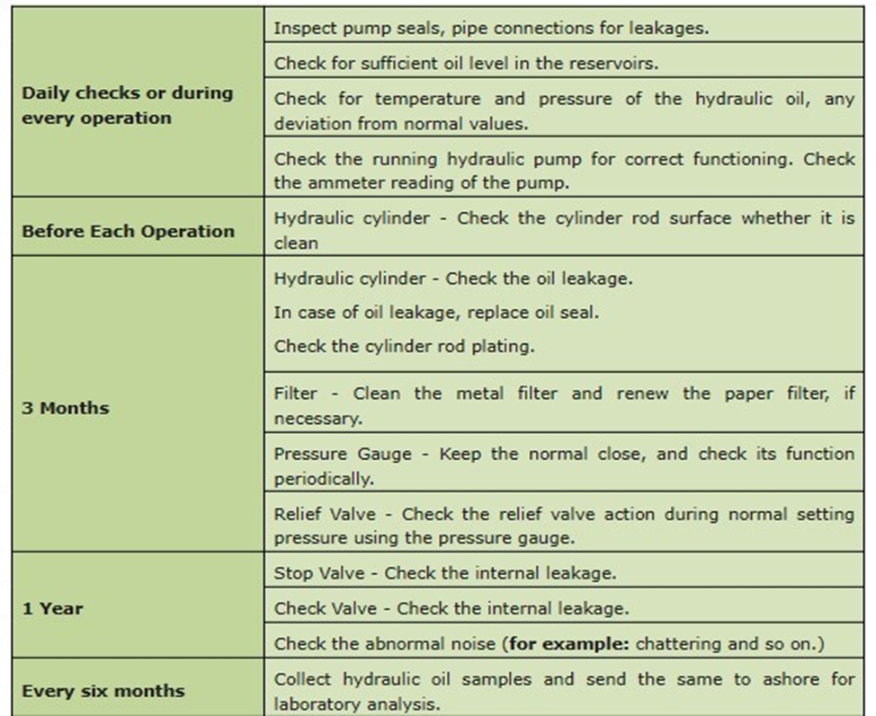
Maintenance schedule for hydraulic systems

General Maintenance:
- During overhaul, take care to prevent foreign matter entry into the system
- Air trap may hinder proper operation. Release air after overhaul before same put in service.
- Maintain proper tightness in all connections with correct sized seal rings
- Secure all piping with suitable clamps to prevent any pipe vibrations
- In case of replacement, use only approved pipes, hoses, securing clamps, fastenings
- Release residual pressure before opening any hydraulic line
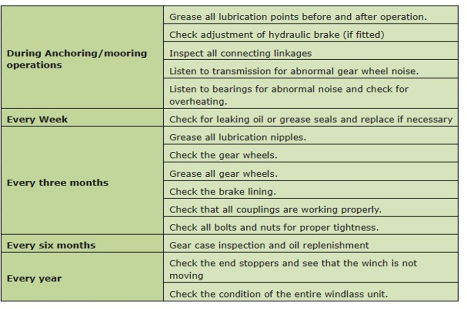
Maintenance schedule for Windlass / Mooring Winch.
Maintenance schedule for Cranes
Maintenance routine for prime mover of deck machineries
- A “prime mover” typically refers to the primary source of power or energy that drives a mechanical system, often used to power machinery.
- Perform routine visual inspections to identify any visible signs of wear, damage, or corrosion on the prime mover and its associated components.
- Ensure that all moving parts are properly lubricated according to the manufacturer’s recommendations.
- Keep a record of lubrication intervals and the type of lubricants used.
- Inspect and clean air filters and intake systems to ensure the prime mover receives a clean and adequate air supply.
- Check the electrical system for loose connections, worn wires, and insulation damage.
- Inspect and maintain the electrical components such as starters, generators, and control systems.
- Regularly perform vibration analysis to detect any abnormal vibrations or imbalances in the prime mover.
- Address any issues identified during vibration analysis promptly to prevent further damage.
- Ensure the proper alignment of the prime mover with the machinery it powers to prevent misalignment-related issues.
- Calibrate controls and sensors to maintain accurate operation.
- Inspect and lubricate bearings as needed, and replace them if they are worn or damaged.
Maintenance of hatch over.
- Drive boxes and electrical enclosures to be checked for water tightness.
- Seals, compression bars and coamings to be inspected and cleaned.
- Drain channels to be cleared regularly.
- In case of hydraulic systems, hydraulic oil must be clean.
- Regular inspection of hydraulic hoses must be done.
- Hydraulic hoses must be replaced periodically as per manufacturer’s guidelines.
- General rust removal on top and sides of the hatch covers, coamings and stays must be thoroughly checked for signs of corrosion and reduction in plate thickness.
- Hatch cover weathertightness must be checked prior every loading.
- Physical damage during cargo operation shall be avoided by careful cargo watch.
- Compression bar must be of an even height with a rounded profile and no sharp edges due to corrosion as this could damage the rubber packing.
- Rubber packing all around the hatch covers and across each panel should be in a good condition, elastic and not hardened.
- Rubber packing should be protected from paint and chemicals.
- Every six months depending on their use, hatch cover wheels should be opened up, cleaned, greased and the bearings renewed if necessary.
Working of an accumulator and its purpose in the hydraulic circuit

Purpose of an Accumulator:
- Accumulator stores the hydraulic fluid under pressure. When the pressure drops in the system, it supplies the hydraulic fluid so that pump supply is maintained.
- By providing an accumulator the requirements of the pump i.e. pump size can be reduced
- Most accumulators operate by compressing a gas.
- Common type is gas filled bladder accumulator.
- Accumulators can also be used to act as buffers on a system to absorb shocks and snub pressure spikes.
- Accumulator acts in similar manner to a capacitor in an electric circuit.
- Danger associated with accumulator is that high pressure may still exist in the circuit even though the pump has been stopped.
Working of an Accumulator:
- The bladder is pre-charged with appropriate gas, usually nitrogen.
- Fully charged bladder closes the poppet valve.
- An accumulator charges when system pressure increases, causing fluid to flow into the accumulator and compressing the nitrogen gas.
- Fluid enters the cylinder until gas and fluid pressure equalize.
- When the system pressure drops, nitrogen in the accumulator expands and sends the fluid out of the accumulator.
- This cycle repeats as per demand.
Advantage and disadvantage of a hydraulic system on board
Advantages:
- It is convenient to transfer power over long distances. For e.g. from central pump room to remote operating sites in the ships.
- A complete local control of operations can be achieved.
- Variable speed control of both linear and rotary motion can be achieved.
- Hydraulic system takes up the load smoothly and continuously transfers power even though speed changes takes place.
- Overload conditions are safeguarded by using a relief valve to limit maximum output torque or force.
- Significant cost savings as the system is flexible in achieving alternative solutions for various requirements.
Disadvantages:
- Area around the system looks messy.
- High pressure hydraulic system poses serious threat of accidents due to its operating pressure.
- Leak in hydraulic system can be the cause of major fires and or explosions.
Effects of the followings on a hydraulic system:- Air in the system / Dirty oil.
Air in the system:
- Air in any hydraulic system must always be avoided.
- Air being compressible gives incorrect balance between units, time lags and irregular operation, which can be dangerous.
- Air in the system is indicated by jerky operation and possible ‘jumping’ at the pressure gauges.
- Air can be kept out with a tight system after proper charging.
- Should air get into the system, it may be removed by purging at various air cocks.
- Total emptying and recharging may be only solution when large quantity of air get access into the system
Dirty oil:
- Filtration and general cleanliness of a hydraulic system is one of the most important features of hydraulic technology.
- Costly breakdown can occur as a result of lack of internal cleanliness leading to dirty oil.
- Debris may be present due to following reasons:
- After major overhaul
- Self-generated debris from the action of pump and valve mechanisms.
- Contamination due to water.
- Generally, acceptable filtration levels for all equipment lie between 10 to 15 microns.
- Such quality filter ensures the system runs for longer period of life with better performance.
Necessity of cooling / heating of hydraulic oil. Or Explain effect of temperature on performance of Hydraulic Machineries
Cooling:
- Coolers are used to reduce the power loss due to heat in the hydraulic circuit.
- A separate cooler is not required for lower powered circuit.
- Placement of tank and piping will help to cause natural dissipation of heat.
- Fore higher power hydraulic system, a seawater or air-cooled heat exchanger is used.
Heating of hydraulic oil:
- Heating of hydraulic oil is done to maintain the viscosity.
- If oil becomes too thin, then adequate lubrication may not be provided for working components.
- If oil is too thick, operation of cylinders may be too slow, starting electrical loads will increase, pressure drop across filters may be excessive.
- Typical hydraulic oil may change viscosity from 30 centi-stokes at 45°C to 500 centi-stokes at -10°C.
Central hydraulic power system supplying various deck machinery

The system consists of:
- Hydraulic pump to convert mechanical into hydraulic energy.
- Valves to allow this hydraulic energy to be controlled.
- Hydraulic motors to convert the hydraulic energy into continuous rotary motion.
- Coolers are used to reduce the power loss due to heat in the hydraulic circuit.
- Relief valve prevents build-up of excessive pressure in the system.
- Ancillary equipment including filters, heat exchangers, tanks, pipes, etc to complete the circuit.
Operation:
- In central hydraulic power system, a number of pumps deliver oil to a main pressure line.
- From this line it will be possible to run any number of motors as long as the oil quantity is big enough.
- Flow control valve helps not to over speed the motors.
Common failure of hydraulic circuit and remedial measures
Common failures of hydraulic circuit:
- Air and Water Contamination
- Temperature Problems
- Fluid Levels and Quality
- Human Error
Air and water Contamination:
- Air contamination is the entrance of air into a hydraulic system and consists of two types — aeration and cavitation.
- Both can cause severe damage to the hydraulic system over time by wearing down the pump and surrounding components, contaminating hydraulic fluids and even overheating the system
- Water caused by system leaks or condensation due to temperature changes.
- Water can degrade hydraulic components over time through oxidation and freeze damage
- A milky appearance in hydraulic fluid can help you identify water contamination.
Fluid Level and Quality:
- Low fluid levels and inappropriate filtration can result in air contamination.
- While fluid contamination can cause temperature problems.
- Leaks can further exacerbate both issues.
Remedial Measures:
- Maintain appropriate fluid level.
- Check fluid samples at regular intervals for contamination. If identified replace fluid.
- Check for any loose connections in the system and rectify.
Temperature Problems:
- Hydraulic system cannot run too hot or too cold.
- If oil becomes too thin due to overheating, then adequate lubrication may not be provided for working components.
- If oil is too thick at low temperatures, operation of cylinders may be too slow, starting electrical loads will increase, pressure drop across filters may be excessive.
Remedial Measures
- Cooler or heat exchangers are used to dissipate excess heat.
- Heating of hydraulic oil is done at low temperatures.
- Typical hydraulic oil may change viscosity from 30 centi-stokes at 45°C to 500 centi-stokes at -10°C.
Human Error:
- Improper installation of any component in a hydraulic system
- Using systems outside their operational capabilities or failing to perform regular maintenance
Remedial Measures:
- Installation must be carried out by well trained and experienced persons, overseen by persons with sound technical knowledge on the system.
- Well planned maintenance system, it’s strict compliance and regular training.
Hydraulic circuit of Deck Cranes and what all safety devices find the safe operation of crane
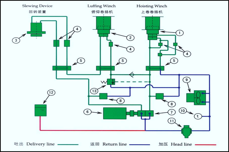
- 1,2,3 – oil motor for hoisting, luffing, slewing winches
- 4- counter balance valve
- 5 – control valve
- 6 – electric motor
- 7 – oil pump
- 8 – relief valve
- 9 – cooler
- 10 – thermo switch
- 11 – filter
- 12 – oil tank
- 13 – unloading valve
Safeties fitted:
- A protection when electric power goes off, brakes are applied. Hydraulic locking by counter balance valve in hydraulic cranes.
- Emergency stop
- Overload safety
- Hoist limit
- Empty drum safe guard (hoisting cable wrapped around the drum at least 3 times to maintain friction to keep lifting capacity)
- A limit switch for highest and lowest position of the jib (max. and min. outreach)
- A turning limit switch (to prevent turning jib from touching other parts of ship)
Hydraulic system used on board for anchor windlass

The system consists of:
- Hydraulic pump to convert mechanical into hydraulic energy.
- Accumulator to supplement the pump supply.
- Oil cooler to dissipate over heat and reduces loss of energy.
- Valves to allow this hydraulic energy to be controlled.
- Hydraulic motors to convert the hydraulic energy into continuous rotary motion.
- Relief valve prevents build-up of excessive pressure in the system.
Operation:
- In hydraulic power system, pumps deliver oil to a main pressure line.
- From this line it will be possible to run motors
- Flow control valve helps not to over speed the motors.
- Levers are provided to change the direction and adjust the speed of the motor.
- The motor converts hydraulic energy into work by rotating the windlass.