STEERING PROCEDURES
Introduction
All steering systems involve sending rudder command signals from the position where the vessel is navigated to the steering gear compartment where the machinery for controlling rudder movement is located. These rudder commands may be manually generated by a pilot/helmsman or electronically
via an automatic pilot.
The method of steering the ship is determined by use of the mode selector switch located on the steering stand. The modes available to send rudder order signals to the steering gear are:
- FOLLOW UP – Manual mode
- NFU – Non follow up mode
- AUTO – Automatic mode
Manual Mode
Manual steering is normally carried out when the vessel is manoeuvring during arrival/departure from a port or during periods of poor visibility. It can also be used in the event of autopilot failure.
In manual mode the ship is steered from the hand steering wheel located on the steering stand located in the centre of the wheelhouse. The hand steering control works in the follow-up mode. An analogue gyrocompass repeater is fitted on the steering stand. A rudder angle indicator is located on the forward
bulkhead. The illumination of the steering stand instrumentation is adjusted by using the associated dimmer control switches.
In follow up mode the steering wheel has a midships position and movement in both port and starboard directions. When the wheel is moved away from the midships position, a rudder command signal is transmitted to the telemotor servo units which puts stroke on the steering gear hydraulic pumps causing
the rudder to move. Once the desired rudder angle is reached an electrical feedback signal from the rudder stops any further movement. As long as the wheel is held in this position the rudder will remain at that angle. Once the wheel is moved to another position, the rudder will follow this command until
it reaches the new position required. For example, if the helm were returned to midships from say 5° to port, the rudder would also return to midships. The rudder is following the steering wheel. This system can only work when rudder feedback signals are available.
Non Follow Up (NFU) Mode
In the NFU mode a basic port or starboard command is given by the use of a spring loaded joystick. The NFU joystick is located at the bottom right hand corner of the steering stand panel. The rudder will move in response to the command from the NFU joystick and continue to do so until the command is removed or the rudder limit reached. When the controller is returned to the midships position, the command is removed and the rudder will remain at the ordered angle. In this mode further port or starboard commands are required to alter the actual rudder angle.
Automatic Mode
In the automatic mode an electronic device produces the rudder command signals to steer the ship. The navigator sets the desired course on the autopilot AD II control panel located on the bridge central console. The system compares the set course with the actual course from the gyrocompass, or possibly from the transmitting magnetic compass. If there is a difference between the set course and the actual course a rudder command signal will be issued resulting in a rudder movement to bring the vessel onto the set course. The AD II is an adaptive autopilot which automatically modifies the steering to changing
external forces such as sea and wind conditions as well as the characteristics of the ship’s hull.
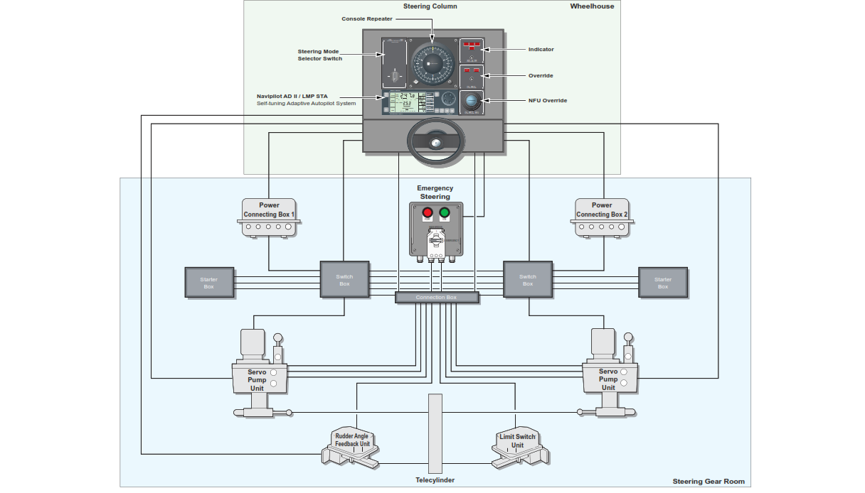
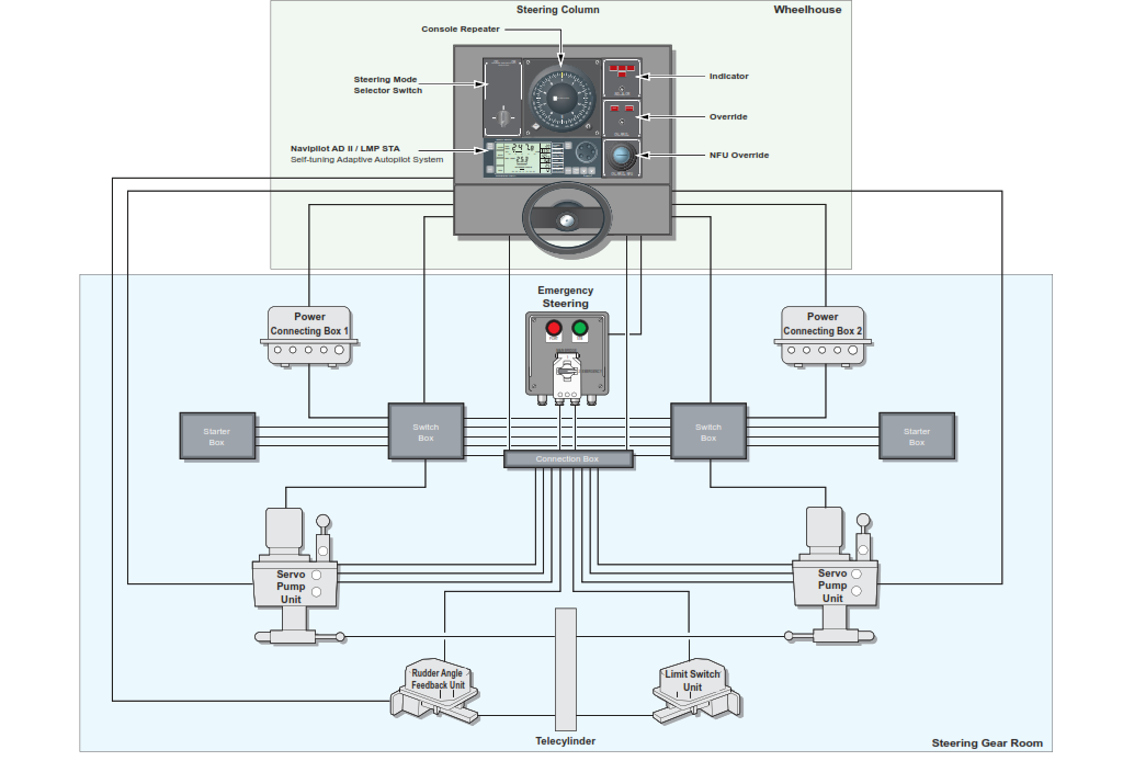
System Configuration
There are a number of system components which make up the steering system.
The AD II control and display unit is located on the steering stand, it sends and receives rudder order information via an interface unit, located inside the steering stand, to the steering gear. It transmits steering data to the voyage data recorder and if a fault occurs sends an alarm signal to the bridge alarm panel.