Check that all hoses and connections are in satisfactory condition and that there are no leaks or soft spots.
The flexible hoses are filled with hydraulic oil. Drain off approx. one cup of oil from the hoses before storage (when disconnecting from the main system). Control bend radius for the flexible hoses during storage (min 800 mm).
Confirm that the units are safely supported, and check that the snap-on coupling and starting head / flow control valves are greased and protected.
Carry out routine maintenance in accordance with maker’s instructions and renew all wear parts at recommended intervals.
Try out the pump every 6 months, and maintain records.
PURGING OF COFFERDAM
Submerged cargo pumps are to be tested for leakage of their mechanical seals and cofferdam with compressed air of suitable pressure as per the maker’s instruction (about 2.0kg/cm2). The test is required to identify the amount of hydraulic oil or cargo leaking from the mechanical seals into the cofferdams. All officers should be aware of the purging requirements and maker’s recommendations.
The test is carried out on the following occasions unless specified otherwise by the pump manufacturer’s manual:
a) After completion of cargo tank cleaning and before loading.
b) 1 or 2 days after loading.
c) Everyday if excessive leakage is detected (a) and (b).
d) Before discharging.
e) After discharging.
f) For long voyages with “no leakage at point b” purge at least every fortnight.
Results of tests must be recorded. After the leak test, the cofferdams are to be kept pressurized with the tank test air, water etc as specified in the pump manufacturer’s manual.
HOW TO PURGE THE COFFERDAM
Place a suitable container underneath the exhaust trap to collect the leakage.
Check that valve and bottom of exhaust trap is not clogged by residue after last purging operation. Stick up with a pin if necessary.
Check that the drain hole from the relief valve on the purging valve block is open. Location design of purging valve is different for the various pump types. For technical details, refer to the pumps service manual.
Connect air or inert gas supply to the snap-on coupling on the purging valve.
Drain the supply line for condensed water.
PUMP MAINTENANCE AND PURGING PRECAUTIONS
Deep well submersible pumps shall be inspected on every occasion after tank cleaning, whenever the opportunity presents. Pumps shall be inspected for loose nuts / bolts and physical condition of the pump body.
Other maintenance shall be carried out as required by the Planned Maintenance System.
Open valve on air / inert gas supply line.
Check that air / inert gas is coming out of the exhaust trap vent line. (Cofferdam is open).
Purging medium shall be such that it is compatible with the properties of the cargo and does not compromise the safety procedures for carriage.
The relief valve on the purging valve block is set to an opening pressure of 3 – 3.5 bar, so a small leakage here is normal.
Maximum pressure of purging medium shall not exceed 3.5 bars.
Purge cofferdam in several sequences if required.
Drain exhaust trap between each sequence.
Disconnect air / inert gas supply.
Close exhaust trap drain valve.
Measure the amount of leakage, -evaluate and log the purging result.
Note: To prevent accidental exposure to the previous cargoes, appropriate level of PPE compatible to the previous cargo shall be worn when purging, overhauling and inspecting cargo pumps.
Not able to purge the cofferdam. (No air, inert gas or liquid coming out of the check pipe when purging)
Possible cause:-
a) No or insufficient pressure of the purging medium
b) Blocked cofferdam.
Note: In case steam is used in attempt to clear a blockage in pump cofferdam system pay special attention not to over pressurize the pump/pipe stack
Remedy:-
a) Check valves, hose connections and purging medium relief valve. (The relief valve opens at approximately 3 -3.5 bar).
b) Check the exhaust trap and the piping on deck for any blockage.
Open if possible.
Disconnect the check pipe from pump unit (lower seal house) – Ensure the system is depressurized prior to this.
Check if the blockage is located in the check pipe or in the pump / pipe stack of the cofferdam.
Depending on the nature of the obstruction blocking the cofferdam, use steam or solvent to dissolve the blockage.
In some case, depending on the severity of the blockage, dismantling of pump might be required.
Leak test the pump after assembly.
Cargo leakage into the pump cofferdam.
Possible cause:-
General Note! Always leak test the pump prior to and after dismantling/ assembling.
This is required to locate possible leakage and to confirm no leakage upon completion of repair.
a) Worn cargo seal
Note: If no leakage is detected by leak test it is likely that the cargo leakage to cofferdam is caused by worn cargo seal. (The upper seal lip is sealing when pressurizing cofferdam.)
b) Leaking seal element in flange connection
c) Crack / pinhole in the piping.
Remedy:-
Leak test pump cofferdam system at approximately. 3 bar pressure.
Check for any leakage, if required do a soap water test.
a) Replace cargo seal set. Additionally, carefully check ceramic sleeve for possible damage or wear down.
b) Check for loose bolts and / or for pitting and corrosion in seal faces.
In case of corrosion repair is required. When assemble, renew damaged seal element.
c) Contact Pump Service Technician.
Hydraulic oil leakage to pump cofferdam.
Possible cause:-
General a) Leaking shaft seal b) Leaking seal element in flange connection. c)Crack/pinhole in piping
Remedy:-
Drain the pump return side prior to dismantling.
Disconnect pump head/unit from pipe stack/casing.
Pressurize pump unit return side at approximate 4 bar and check for leakage to cofferdam side. Leak test pump pipe stack / casing at max 7 bar on cofferdam side and check for leakage to return side.
a) Replace shaft seal (replaced seal to be reconditioned if feasible)
b) Check sealing surface for possible damage – repair if damaged. When assemble, renew damaged seal element.
c) Contact a Service Station.
EVALUATION OF THE PURGING RESULT
1. Cargo leakage
Cargo in the cofferdam can come from shaft seals, flange face seals in pipe stack / pump head or damage (cracks) on the pipe stack / pump head.
A small leakage rate over the shaft seals up to about 0.5 L/day during pump operation is normal, and replacement of seals should not be necessary with this leakage rate. For short periods of time, higher leakage peaks can occur.
The leakage rate is also dependant on the type of cargo. Some cargoes like naphta, condensate etc., penetrate the shaft seals more easily than lub. oils, vegetable oils and other viscous cargoes. If the leakage rate is up to about 2 liters/day, the pump must be purged a couple of times daily, and inspected as soon as possible to find the reason for the leakage.
Intensify the purging if the leakage rate is increasing above acceptable level. If this is not keeping the leakage under control, close the hydraulic service valve.
Do not operate the pump, use the portable pump to discharge the cargo. The development of a cargo leakage can be followed if purging is done according to specified intervals. Thereby maintenance work can be planned, and unexpected shut down due to leakage can be avoided.
2. HYDRAULIC OIL LEAKAGE
Hydraulic oil in the cofferdam can come from shaft seals, flange face seals in pipe stack / pump head or damage (cracks) on the pipe stack/pump head.
A small leakage rate into the cofferdam up to about 10ml/h (0.25 L/day) from the mechanical oil seal or lip seal during pump operation is normal. For short periods of time, higher leakage peaks can occur.
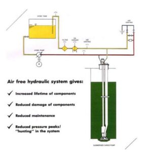
AIR IN THE HYDRAULIC SYSTEM
1. HOW TO DETECT AIR IN THE SYSTEM
1) Cargo Pump will not start from remote. >> Possible
2) Level Variations in the hydraulic oil tank at different system pressure. >> Yes
3) Back flow to hydraulic oil tank during stand still.>>Yes
4) Foaming in the hydraulic oil tank. >>Yes
5) Oil sample “milky” / white, or air bubble mixed into the oil. >>Yes
6) Abnormal noise from hydraulic pumps or motors. >>Possible
7) Uncontrolled pressure variations (hunting) during operation. >>Possible
8) Pressure peaks / shock in the system during start / stop of consumers. >>Possible
2. AIR VENTING FROM THE HYDRAULIC SYSTEM