Modern ships vary considerably in details of their construction, according to their size and type, but almost all conform to basic systems of construction. They are all designed to cater to the intended use including:
■ Type of cargoes and / or passengers to be carried
■ Area of operation,
■ Framing systems,
■ Sub division and
■ General arrangement of the engine room and the accommodation.
Ship construction has always been an art. From the first boat carved out of a solid log, man has innovated to meet his need of sea transport. As the ships started becoming bigger, a need was felt to develop specifications of materials and methods and principles of construction. As the ships started venturing away into the ocean, strength and stability had to be designed into the ship. All this eventually developed into the science of Naval Architecture.
Ship construction as an assembly unit
Ships are constructed in shipyards, which are specialised industrial units engaged in design, assembly and construction of ships. As you look around your ship, you will see that the ship means all kinds of equipment, material and facilities. Invariably the shipyard is not able to manufacture all these. The shipyard therefore, in its design stage, decides what is needed, who is to supply it and how it is to be put together. This included even steel components. The efficiency of the shipyard therefore lies in its ability to get the suppliers to bring their equipment etc and to put it together just in time.
During World War II, the Allies needed a lot of ships and they needed them very fast. The only other industry at that time excelling in assembly art was the car manufacturers. It was therefore decided that they should be asked to plan, design and establish such units. The allies built hundreds of ships on an assembly plant style thereafter and every such ship was completed in eighteen days from keel laying to sailing. Notable part of the story is that the ships were constructed to perform at least one voyage across the Atlantic and even after 20 years a large number of these ships were still plying. The ships were called Liberty, Victory and Ford ships.
Ship as a box
We looked at the various parts of the ship in the last semester. You have now been on the ship for some time. You must have noted that the ship is a floating box with pointed shapes at the fore and after end. It is pointed or streamlined as it is called, at the bow, so that the ship can cut through the water with ease and it is shaped at the stern to provide for effective functioning of the propeller and the rudder.
The naval architect therefore has to consider and provide for the stresses caused due to:
■ This box floating in the water with unevenly distributed weights,
■ Rolling and pitching, and
■ Generally be sturdy to serve as cargo / passenger carrier for a number of years.
The ship is strengthened in various ways to withstand the stresses, which are expected. These are various framing system:
► Double bottom
► Frames & beams
► Watertight bulkheads
► Hatchways
► Bilge keels
► Peaks and panting arrangements
► Stems
► Rudders and stern frames
► Sterns
► Stern tubes and propellers
► Hatch beams and covers
► Hawse pipes & ventilators
► Pipes to tanks and bilges
Ship as a box girder
A ship when considered, as a structural unit is a girder, a box or beam girder, composed of many small girders, frames and beams. It is braced, supported and tied together so that the strength of the ship as a whole is dependent upon the effectiveness of all these members.
However, any ship is no stronger than her weakest component. Some parts are more vital to the floating structure than others. The science of naval architecture is directed to designing and assembling. Several parts of the vessel are brought together and assembled in a practical and economical manner.
Such design and consequent construction needs to satisfy:
► The regulations laid down by the Administration and the classification societies, consistent with strength, rigidity and seaworthiness,
► The earning capacity in terms of carriage of cargo or passengers
► Light weight conditions (additional weights reduce the carrying capacity and increase the fuel consumption)
► The speed and fuel consumption parameters.
Longitudinal Stresses
(Fig 1) below represents a narrow steel plate. The ends resting on supports A and B. It is a simple girder and if a heavy load C be applied at its middle point, (Fig 2.), the edges of the plate will be subjected to stresses, compression on its upper edge and tension on its lower edge.
Should the load be excessive the upper edge would crumple up and the lower edge break asunder. The girder would be fractured under strain.
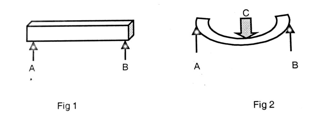
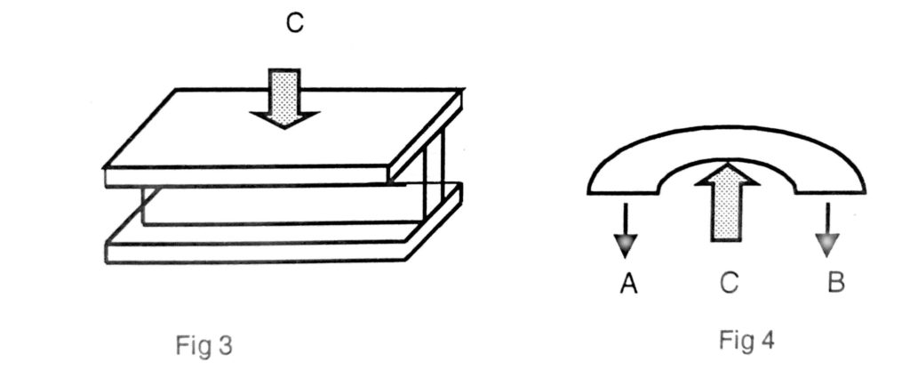
By stiffening the edges of the plate with flanges as in Fig.3, the girder will now be able to resist distortion due to the weight C. The vertical plate is called the web of the girder and the edge angles its flanges. The web could now be, made thinner and the arrangement gives a more efficient girder than the simple plate. A converse condition would arise when the girder, supported at its middle point A, is called upon to support loads B and C at each end as in Fig 4.
A ship when afloat is subjected to similar stresses, not merely by the loads placed on board but more seriously when working in a seaway, especially when supported by waves at the extremities or in the middle.
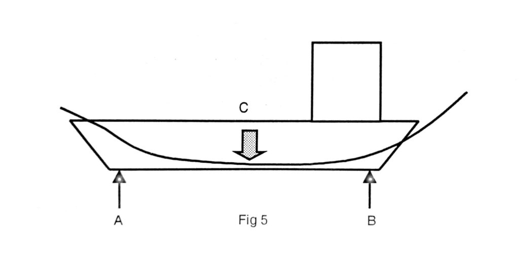
The load is, of course, not concentrated but is distributed over the length in various degrees of concentration. If the crest of two waves, one at each end supports the vessel, the upper edge of the ship is under compression, and the lower edge under tension.
If the hull of the ship were not made strong enough to resist these stresses she would bend downwards at the middle of her length. This is called “SAGGING”, as shown in figure 5.
When the ship is supported amidships on the crest of a single wave as shown in fig 6, with the ends B and C unsupported, the stresses are changed to tension on the upper edge and compression on the lower edge. if the hull were not made strong, it would suffer excessive stresses at the middle of the length. This is called “HOGGING”.

Fig 6 These longitudinal stresses occur alternately when a ship is among waves. The ship therefore has to be specially strengthened and stiffened in order to make the hull strong enough to withstand all normal hogging and sagging stresses. Along the length of her strength deck “sheer strake”, “stringers”, etc. are used while strengthening along the lower edge is done by means of “centre keel”, “keelsons” and “longitudinals”.
Transverse Stresses
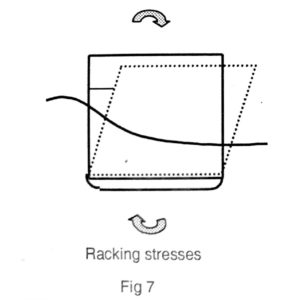
The ship is also subjected to transverse racking stresses when rolling in a seaway, the tendency of which is to cause distortion at the corners of the box-shaped girder. A simple transverse section consists of a “frame’, or rib, extending the whole girth of the ship, the top ends being held firmly in position by means of a transverse beam.
The beam is connected to the frame by means of a bracket called a beam “knee”, which is made triangular in shape and of sufficient depth and breadth to get a good connection to the beam and to the frame. The strain of RACKING (fig 7) is likely to be more evident at the top corners than at the bottom part of a transverse section. The upper works are relatively weaker owing to deck openings and other sources of weakness. Whereas the “floor” and “bilge” brackets make the bottom part of the section more solid and rigid.
Collapsing Stress
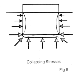
The water presses inwards on every submerged part of the ship in a direction perpendicular to the skin surface, with a force, which increases directly in proportion to the depth. The function of the skeleton framework of the ship is to keep the shell plating to its designed shape. The plating is comparatively thin and flexible and it might readily yield inwards to the pressure of the water were it not for the frames and other stiffeners. (Fig 8)
When the ship is under way the plating has to push the water away at the bows, and in doing so have A tendency to vibrate, or to move in and out, this movement is called “PANTING”. When the ship is pitching into a head sea excessive pounding is set up forward and aft when she rises and falls. The racing of the propeller aggravates the local stresses at the stern. Evidence of this is made obvious on occasions by strained plating. (And slack rivets on riveted vessels).
The ship girder is, therefore, specially strengthened at the ends by means of “panting” beams, thickened plating, “breast hooks”, “crutches”, closer spacing of frames, stringers, deeper floors, etc., to enable the shell plating to resist its tendency to flexibility when subjected to panting stress. The concentration of heavy weight along the middle line of the hold introduces a collapsing stress, which tends to draw the two sides of the ship together.
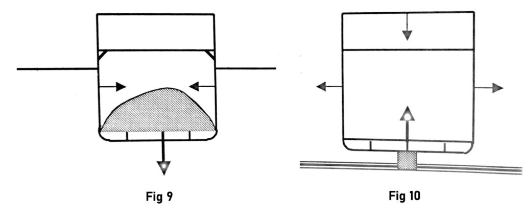
The fact was noticeable when sailing ships loaded heavy cargoes such as nitrate in Chile, copper ore in Australia, etc. The lower layers of such cargoes were usually stowed out to the bilges and gradually narrowed towards the middle line, leaving a space between the cargo and the ship’s sides as in Fig.9. The rigging invariably slackened when the vessel was loaded and had to be tightened up by taking a turn or two of the box screws of each shroud and backstay. The fact was usually noted in the chief officer’s logbook as a reminder that the rigging had to be slackened back again before the cargo was discharged, thus allowing the hull freedom to resume its original shape.
The opposite effect is created when a ship is in dry dock. The weight of the hull on the keel block pushes the bottom of the vessel upwards, which tends the sides to bulge outwards, hence the necessity for supporting the bilges with bilge blocks and shoring sides to assist the hull to keep its shape. (Fig 10)
Torsion stresses occur when a body is subjected to twisting moment, which is commonly referred to as torque. This occurs when a ship heading at 45 degrees to the swell is subjected to righting moments in opposite directions because when the forward end of the vessel is sliding down the crest of a wave the stern will be climbing up the crest.
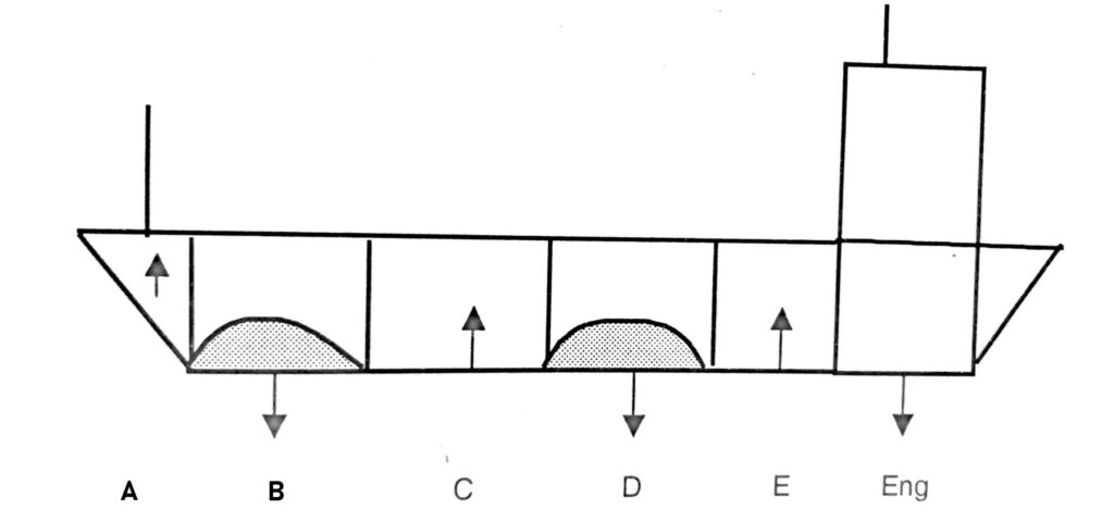
Local Stresses
Stresses are also set up when weights are unequally distributed in the ship as in Fig. 11. This occurs because some compartments are empty and others laden with cargo. Unequal vertical stresses are thus created. A downward pressure in the laden compartments and upwards pressure in the empty ones. The ship floats at a mean draught, which corresponds, to the weight of the hull and its contents. Suppose it were possible to disconnect the several compartments. Let each one, with its own buoyancy and weights float upright. Then the loaded compartments a D, and the engine room would come to rest at a deeper draught than the mean draught, and the lighter compartments A C and E would float at a draught lighter than the mean draught.
Localised stresses are also set up in the way of deck machinery such as windlass, cargo winches, derricks, steering gear, at break of accommodation etc. The structure in their vicinity is stiffened by thickening the plating, putting in additional or stronger beams, and arranging the material so that the local stress may be distributed to adjacent parts and not localised at one place. High stresses occur where there is discontinuity of the hull girder such as, sudden breaks in the bulwarks or where longitudinals meet transverse bulkheads.
This very general and brief reference to the stresses thrown upon the ship’s hull has proved to you that the longitudinal and transverse framework of the ship is designed to enable the shell plating to keep its form and to resist any distortion and strain. The structure must, therefore, be made rigid enough longitudinally and transversely to withstand all the normal stresses to be expected when the ship is labouring at sea with her cargo intelligently distributed and securely stowed.