

Introduction
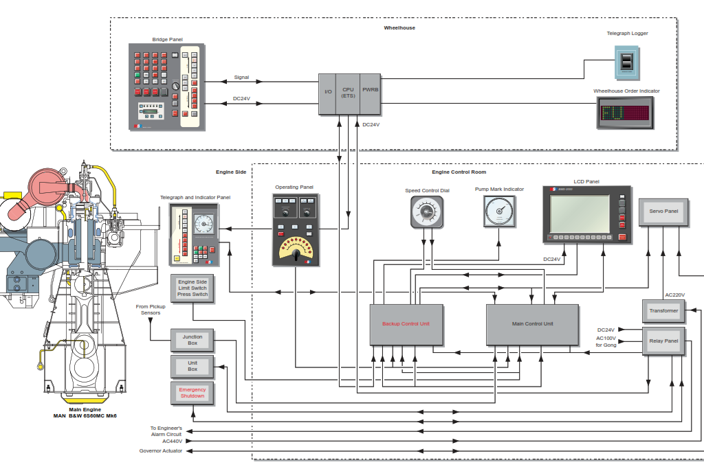
The BMS-2000 Bridge Manoeuvring System is a manoeuvring system used for the remote control of the ship’s main diesel engine. The BMS-2000 allows for remote engine control from the wheelhouse or engine control room. Control may be transferred between these stations and may also be transferred to the local engine side control stand. The local control stand overrides requests for control from all the positions and is not dependant on the correct functioning of the BMS-2000 system.
The BMS-2000 is composed of five sub-systems as follows:
- The Engine Control System (ECS) which provides full automatic control from the wheelhouse.
- The Engine Protecting System (EPS) which monitors the engine systems and initiates alarms, engine slowdown or engine shutdown in the event of extreme conditions which could cause engine damage.
- The Engine Telegraph System (ETS) which provides communication between the wheelhouse and engine control room and the engine side control stand.
- The Engine Manoeuvring System (EMS) which provides for manual control of the main engine from the engine control room.
- Electronic Governor System (MAG) which regulates the fuel supply to the engine cylinders in order to control the engine’s speed.
The functions of all of these systems is detailed in section 2.1 of the machinery manual. However an explanation of the control stations, wheelhouse, engine control room and local control stand as well as the engine control system and the engine telegraph system are included below.
Prior to Starting the Main Engine
The main engine will normally be kept in a state or readiness by the engineering staff unless maintenance is to be carried out on it. To maintain the engine in this state a numbed of systems will be operating.
Lubricating Oil System
One of the main engine lubricating oil circulating pumps will normally be running. This will assist in even cool down after arrival in port and also help maintain the lubricating oil at its operating temperature.
Fresh Water Cooling System
One of the main fresh water jacket cooling pumps will normally be running. When the engine is not running the water will be heated by a steam heater.
The main jacket water system is common with the generator engine cooling system, so if the auxiliary boilers are not on the generator engines will act as a limited heat source for the water.
Fuel System
The main engine can be operated on marine diesel oil (MDO) but it is normal for it to run on heavy fuel oil (HFO). HFO needs to be heated to attain the correct viscosity for injection so the oil is circulated through the engine’s supply and return pipes, through a steam heater and the service tank. The fuel
lines are also steam trace heated.
Steam System
One of the auxiliary boilers will normally be in operation to maintain the fuel oil and jacket water temperatures.
Starting Air System
The start air system normally operates with one air receiver in use and one receiver isolated to ensure there is always a reserve of air available. However when the engine is shutdown, the starting air system is isolated.
Preparation for Start
Turning Gear
Prior to standby the engine will be turned over using the turning gear, which engages pinion wheel on the flywheel and driven by an electric motor. This slow turning will expel any liquids that may be present in the cylinders vial the indicator cocks. The turning rear is interlocked with the starting air system.
The starting air start system is inhibited if the turning gear is engaged.
Starting Air
Once the turning gear is removed, and providing all the systems above are operational, the starting air system will be opened up.
Blowing Over on Air
The final check prior to declaring the engine ready to run is to blow the engine over on air with the indicator cocks open. On completion of the turning on air the indicator cocks will be closed and the duty engineer will signal to the wheelhouse via the telegraph that the engine is ready.
Barred Range
The barred range is the speed at which the engine will vibrate excessively. The engine is never run between these limits.
Load Up Program
Once the ship is free to move to full sea speed (navigation full) an automatic load programme will gradually increase the engine’s speed to the set value. On the approach to port the engine speed is reduced manually by the duty engineer to manoeuvring speed.
Finished With Engines
When the command for finished with engines (FWE) is issued the engine will be shut down and prevented from being able to be started. A time will be agreed for notice to start the engine so the engineers can plan what maintenance may be carried out.
The speed control dial in the engine control room must be turned to the STOP position and the speed setting handwheel at the local engine side control stand must be set to the STOP position if it is engaged. The telegraph transmitter and receivers must be set at the STOP positions.
The starting air system must be closed and the lines must be vented.


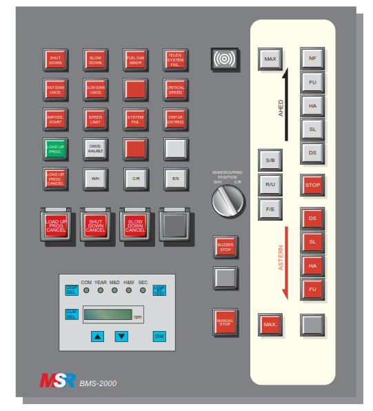
The bridge BMS-2000 engine manoeuvring panel is fitted in the main wheelhouse console and contains a telegraph transmitter unit and other devices for operating and monitoring the main engine.
The telegraph transmitter unit is pushbutton operated with illuminated indicators for the selection of each engine speed, ahead or astern. When the telegraph pushbutton selects a new position the indicator is illuminated showing which movement has been selected. When in wheelhouse control, movement of the telegraph transmitter to a new position automatically activates the control
system to operate the main engine according to the new order.
The sub-telegraph has three illuminated pushbuttons located to the left of the main telegraph transmitter. These are S/B (Standby), R/U (Run up) and F/E (Finished with engines). When any of these pushbuttons is pressed the indicator illuminates.
The manoeuvring panel includes an emergency stop pushbutton marked MANUAL STOP , and a buzzer stop pushbutton. In addition there is a selector switch for selecting the engine manoeuvring position, either the wheelhouse (W/H) or the engine control room (C/R).
At the bottom left of the wheelhouse manoeuvring panel the Telegraph Logger front panel is located. This provides a printout of all engine movement instructions on a paper roll. The panel contains a dimmer pushbutton, a lamp and buzzer test pushbutton, a selector pushbutton for Month/Day or Hour/Min and a display selector pushbutton for changing the display from engine RPM to time or vice versa. Two arrow pushbuttons allow for setting of the time when the display is showing the time. Five LEDs at the top of the telegraph logger panel show which features are selected.
At the rear of the telegraph logger there are switches and pushbuttons associated with the printer unit; these are a test print pushbutton, a wind pushbutton, a reset pushbutton and a FREE/LOCK selector switch. When LOCK is selected printing is not done but 100 lines of printing content are memorised.
The bridge manoeuvring console also contains the Oil Mist Slowdown panel. This contains two illuminated indicators for Oil Mist Slowdown and Oil Mist Slowdown Cancel. There is a LAMP TEST pushbutton and an OIL MIST SLOWDOWN CANCEL pushbutton which is pressed if the wheelhouse
desires to cancel the automatic oil mist slowdown. The panel also has a dimmer dial.