
Shipboard electrical distribution system

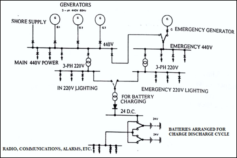
- The electrical power system on board a ship is designed to provide a secure supply to all loads.
- The general scheme of a ship’s electrical power system is common to nearly all ships.
- Both auxiliary and emergency services are supplied are by the main generators during normal operating condition.
- In the event of emergency only, the emergency services are supplied by the emergency generator.
- The emergency supplies comprise of:
- Emergency Lights
- Navigation Lights
- Navigational Aids
- Radio Equipment
- Alarms & Control Systems etc.
- A back up 24 V D.C supply is also available.
Parallel operation of Generators. Necessary conditions required prior to the synchronizing of electrical alternators
- Connecting more than one alternator to the common bus bars is called ‘synchronising’ and this enables the parallel operation of the alternator.
- Following condition must be fulfilled for paralleling the alternator:
- Voltage must be correct
- Frequency must match
- Phase sequence should be correct
- When the voltages are same, frequency matches and the syncroscope is near stationery at the 11’O clock position, the circuit breaker of the incoming alternator must be closed.
- The incoming alternator should have the same parameters as the running alternator.
- If the speed of the incoming machine is different, the governor control switch should be used to adjust the speed.

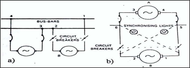
A – Two alternators about to be connected in parallel.
B – The same machines showing possible arrangement of synchronizing lights.
Purpose of providing circuit breakers and fuses in electrical distribution system
Fuses:
- The primary use of an electric fuse is to protect electrical equipment from excessive current and to prevent short circuits or mismatched loads.
- Apart from protecting equipment, they are also used as safety measures to prevent any safety hazards to personnel.
- There are two types of fuses namely rewireable fuses and cartridge fuses.

Rewireable fuses:
- When current through a fuse wire exceeds its rated value, then it produces sufficient heat in the fuse wire.
- When the temperature raises above the melting temperature of the fuse wire, the fuse melts and faulty circuit is isolated from the supply.
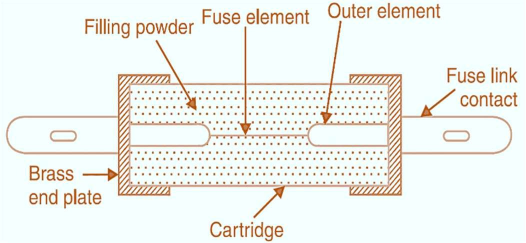
Cartridge fuses:
- These are totally enclosed ceramic tubes filled in with quartz power. The fuse wire is of silver.
- The arc which is produced during the fusing operation is immediately extinguished by the quartz powder and it does not come into contact with the surroundings due to the ceramic enclosure.
Circuit Breakers:

- Fuses are suitable for protection against only heavy fault currents due to short circuit.
- Fuses are not suitable for protection against overheating, leakage current, under voltage, unbalanced loads etc.
- For obtaining protection against such faults, circuit breakers are used.
- A number of relays are used which detect the appropriate fault and produce a signal which is fed to the circuit breaker.
- Thus, circuit breaker can operate over a very wide range of faults including short circuit.
- It is also provided with manual ON/OFF operation.
- Circuit breakers are provided with generators, main switch boards and other heavy loads.
- Air Circuit Breaker (ACB), Air Blast Circuit Breakers (ABCB), Oil Circuit Breaker (OCB) etc. are some types of circuit breakers.
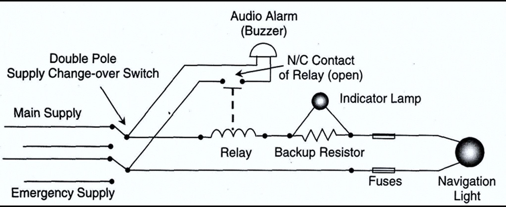
Arrangement of navigation light circuit with indications and alarms


- The Navigation Light Indicator Panel has indicator lamps and an audible alarm to warn of any lamp or lamp- circuit failure.
- When the double pole switch is closed the navigation light is illuminated.
- Current in the relay circuit causes the relay coil to energise, which pulls the NC (normally closed) contact open so that the audio alarm (buzzer) circuit is now open.
- Only a low voltage lamp is needed for the indicating lamp.
- This ensures a small voltage drop across that part of the circuit.
- If the indicating lamp fails, the circuit is completed through the back-up resistor, so the navigation light does not fail.
- If the navigation light fails, or if a fuse blows, the current in the circuit ceases and the relay is de-energised.
- The NC contact springs back to activate the buzzer circuit.
- In case of failure of the ship’s mains, the double pole switch may be changed over to emergency supply.
- Purpose and application of the following:
- ACB.
- MCB.
- Fuses.
- MCCB.
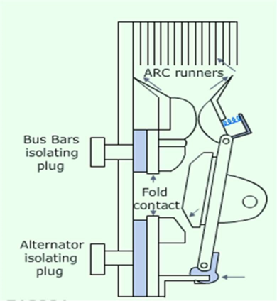
Air Circuit Breaker (ACB):
- These breakers are important safety device on generators. Their function is
- The main feature of ACB is that it dampens or quenches the arcing during overloading
- Open and close a 3-phase circuit, manually or automatically.
- Open the circuit automatically when a fault occurs. Faults can be of various types – under or over voltage, under or over frequency, short circuit, reverse power, earth fault etc.
Miniature Circuit Breakers (MCB):
- For low voltage and low power applications MCB’s are used.
- These are generally used for domestic purposes.
- These are single phase circuit breakers.
Moulded Care Circuit Breakers (MCCB)
- These are also low voltage and low power application circuit breakers.
- MCCBs are suitable for protection of Main branch and feeder circuit & connected equipment / load.
- It is designed for use in Switchboards, Control Panels and in separate enclosures to meets the requirements of lighting, distribution and power circuits.
Care and maintenance lead acid batteries
The life of a battery can be extended with proper maintenance and taking good care of it. The following steps should be followed for the maintenance of a battery:
- Always store or recharge batteries in a well-ventilated area away from sparks or open flames.
- Top side of the battery should be clean and dry.
- Keep the vents clear and free from deposits.
- Always keep lead acid battery vent caps securely in place.
- Pour concentrated acid slowly into water and never add water directly into the acid
- Keep terminal connections tight, free from corrosion and coat with petroleum jelly.
- Maintain fully charged lead acid battery on trickle charge as they suffer internal discharge.
- Check the terminal voltage of the lead acid battery regularly.
- Fully charged battery will have a terminal voltage of 2.2 volts.
- Damaged lead acid batteries shall be kept in properly labelled acid-resistant structures.
- Chargers that are designed for that particular battery should be used
- Do not store acid in hot locations or in direct sunlight.
- Use only non-metallic containers and funnels.
Procedure for starting emergency generator manually

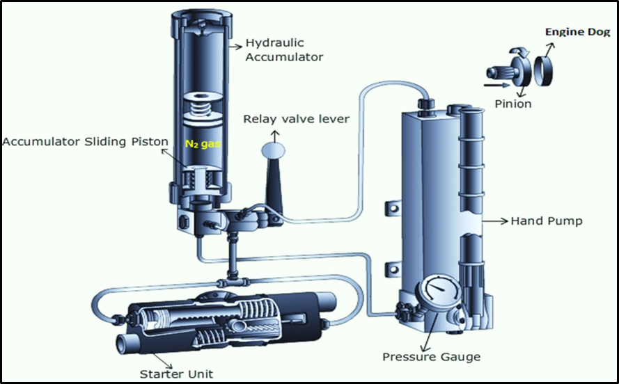
Starting the emergency Generator by hydraulic start:
- Put the switch in manual mode and check the pressure gauge for sufficient oil pressure.
- Open the valve from accumulator to generator.
- Push the spring-loaded valve and the generator should start.
- Check voltage and frequency.
- Keep the generator running for 10–15 min and check the exhaust temp and other parameters.
- Check the sump level
- For stopping, use the manual stop button from the panel.
- After stopping the generator, pressurize the hydraulic accumulator to desired pressure.
- Close the valve from accumulator to generator.
Requirements for navigation lights
- The navigation lights must be connected directly or through a transformer to the main or emergency switchboard i.e., no switches are to be in between the source and the dedicated distribution board.
- The distribution board must be easily accessible to the officer of the watch.
- The masthead, side and stern lights shall be connected separately to the above distribution board which is reserved for this purpose.
- Each light shall be controlled’ and protected in each insulated pole by a switch and fuses or by a circuit breaker mounted on the above distribution board (in case of failure of the ship’s mains, the double pole switch may be changed over to an emergency source of supply).
- Each light shall be controlled’ and protected in each insulated pole by a switch and fuses or by a circuit breaker mounted on the above distribution board (in case of failure of the ship’s mains, the double pole switch may be changed over to an emergency source of supply).
- The Navigation Light Indicator Panel has indicator lamps and an audible alarm to warn of any lamp or lamp- circuit failure.
- Each lamp-circuit has an alarm relay which monitors the lamp’s current. The relay may be electromagnetic or electronic.

| Range of visibility (luminous range) of light in nautical miles | Luminous intensity of light in candelas for K = 0.8 |
| 1 | 0.9 |
| 2 | 4.3 |
| 3 | 12 |
| 4 | 27 |
| 5 | 52 |
| 6 | 94 |
SOLAS requirements for the emergency power supply system fitted on ships
- A self-contained emergency source of electrical power shall be provided
- The emergency source of electrical power, associated transforming equipment and switchboard shall be located above the uppermost continuous deck.
- It shall be readily accessible from the open deck.
- They shall not be located forward of the collision bulkhead.
- No interference shall take place with supply and distribution of emergency source of electrical power in the event of fire in the location of the main source of electrical power and its associated equipment.
- Following services shall be provided by the emergency power supply:
- At least for 3hr emergency lighting at every muster and embarkation station and over the sides
- At least for 18hr:
- Emergency lighting in accommodation alleyways, stairways and exits, machinery spaces and main generating stations, all control stations, machinery control rooms, and at each main and emergency switchboard, stowage positions for firemen’s outfits, at the steering gear, emergency fire pump and emergency fire pump location, cargo pump room location.
- Navigation lights, MF/HF, ship earth station and VHF.
- All internal communications, fire alarm and fire panel.
- intermittent operation of the daylight signalling lamp, the ship’s whistle, the manually operated call points.
- For a period of 18 h one of the fire pumps
- The emergency source of electrical power may be either a generator or an accumulator battery.
- Where the emergency source of electrical power is a generator, it shall be driven by a suitable prime mover with an independent supply of fuel, having a flashpoint of not less than 43°C.
- The emergency switchboard shall be installed as near as is practicable to the emergency source of electrical power.
- No accumulator battery fitted in accordance with this regulation shall be installed in the same space as the emergency switchboard.
Type of cumulative damage that may be caused when alternators are incorrectly synchronized
- When alternators are incorrectly synchronized, it can lead damage both to the alternators themselves and to the power system they are connected to.
- Synchronization is crucial in power generation to ensure that multiple generators work together seamlessly.
Mechanical Damage:
- Mechanical damage can occur due to differences in rotor speeds between alternators that are not synchronized.
- When two or more generators are connected in parallel, their rotors must rotate at the same speed.
- If synchronization is incorrect, it can cause mechanical stress, such as shaft torsion and bending, which may lead to long-term wear and eventual failure of the rotating machinery.
Electrical & Electronic Damage:
- Incorrect synchronization can result in voltage and frequency mismatches between the alternators and the power grid.
- This can lead to electrical damage, including overvoltage or undervoltage conditions, which can cause insulation breakdown and damage to sensitive electrical components.
- Frequent voltage and frequency deviations can damage electronic equipment and disrupt the operation of the entire power system.
Resonance and Vibration:
- Misalignment of alternators can create electrical and mechanical resonances within the system.
- These resonances can lead to increased vibration and stress on the alternators and connected equipment, potentially causing cumulative structural damage over time.
Loss of Efficiency:
- Incorrect synchronization can lead to decreased overall system efficiency.
- Inefficiencies can result in higher operating costs, as more fuel or energy may be required to produce the same amount of power, and this inefficiency can persist over time.
Principle of operation of a Transformer? Why it is required in a distribution system?
Purpose of Transformer in a distribution system:
- It is a device that transfers electric energy from one alternating current circuit to one or more circuits, either increasing or reducing the voltage.
- Transformer are used to reduce the voltage of conventional power circuit to operate low voltage devices.
- It is also used to raise the voltage from electric generators so that electric power can be transmitted over long distance
Working Principle:
- Transformer works on Faraday’s law of mutual induction.
- Faraday’s law of electromagnetic induction states that, when a change takes place in the magnetic flux which is linked with a circuit, an electromotive force current will induce in the circuit.

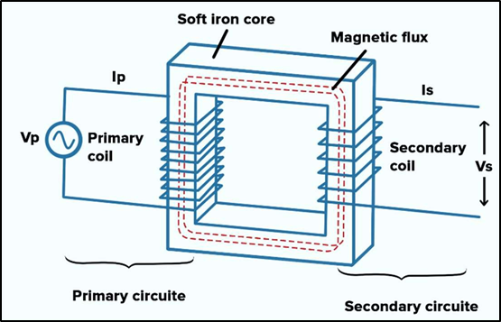
- The transformer consists of two separate winding placed over the laminated silicon steel core.
- The winding to which AC supply is connected is called primary winding and to which load is connected is called secondary winding.
- It works on the alternating current only because an alternating flux is required for mutual induction between the two winding.
- When the AC supply is given to the primary winding with a certain voltage, an alternating flux sets up in the core of the transformer, which links with the secondary winding and as a result of it, an emf is induced in it called Mutually Induced emf.
- The direction of this induced emf is opposite to the applied voltage.
Operation of Emergency compressor:
- An emergency air compressor is used for starting the auxiliary engine at the time of an emergency or when the main air compressor has failed for filling up the main air receiver.
- It has no connection between the main air bottle.
- This type of compressor can be motor driven or engine driven.
- If the motor is driven, it should be supplied from an emergency source of power.
- Emergency air compressors are typically designed to start automatically when a loss of pressure or an emergency situation is detected.
- These compressors are equipped with pressure sensors and control systems that monitor the air pressure in the system.
- If pressure drops below a certain level or other emergency conditions are detected, the compressor is automatically started.
- It can also get power supply from emergency switch board.
- Safety systems are in place to prevent overpressure, overheating, or other issues that may arise during compressor operation.
- These systems can include pressure relief valves and temperature sensors.
Various safeties fitted on main switch board
Dead front Panels:
- It’s a safety device provided on the Main switch board individual panels wherein you cannot open the panel until the power of that panel is switched off.
Fuses:
- The primary use of an electric fuse is to protect electrical equipment from excessive current and to prevent short circuits or mismatched loads.
- Apart from protecting equipment, they are also used as safety measures to prevent any safety hazards to personnel.
Over Current Relays:
- OCR is used mainly on the local panel and MSB for protection from high current.
- They are installed where a low power signal is a controller.
- Normally relays are set equivalent to full load current with time delay.
Circuit breakers:
- A circuit breaker is an auto shut down device which activates during an abnormality in the electrical circuit.
- Especially during overloading or short circuit, the circuit breaker opens the supplied circuit from MSB and thus protects the same.
- Different circuit breakers are strategically installed at various locations.
Earth fault indicators:
- It is a situation where the current-carrying conductor comes directly in contact with the earth’s surface.
- Indicators are provided in MSB to indicate earth faults
Other safety devices on MSB are:
- Under Voltage relay,
- Reverse power trip,
- Preferential trip,
- Over current trip,
- Short circuit trip,
- Arc chute,
- Ebonite rod (to remove static charge)